Expansion-controlled joints in airbags for out-of-position occupants and cushion positioning

an airbag and expansion control technology, applied in the direction of pedestrian/occupant safety arrangement, vehicular safety arrangments, vehicle components, etc., can solve the problems of increasing the risk of injury to out-of-position occupants, affecting the placement of seats, and occupants may experience an impact on the interior of the seatbelt, so as to reduce the probability of injury

Inactive Publication Date: 2007-03-27
AUTOLIV ASP INC
View PDF18 Cites 58 Cited by
  • Summary
  • Abstract
  • Description
  • Claims
  • Application Information

AI Technical Summary

Benefits of technology

[0011]The apparatus and method of the present invention have been developed in response to the present state of the art, and in particular, in response to the problems and needs in the art that have not yet been fully solved by currently available airbag cushion deployment restraint systems, including internal tether systems such as internal break-tether systems. Thus, the present invention provides novel deployment restraint systems having expansion-controlled joints and airbag cushions incorporating such systems used to reduce the probability of injury to an out-of-position vehicle occupant during the deployment of an airbag cushion.

Problems solved by technology

In more severe collisions, however, even belted occupants may experience an impact with the car's interior.
This inflation process is generally difficult to regulate, however, and some regions of the cushion may inflate before others, increasing the risk of injury to out-of-position occupants located near these early-filling portions of the cushion.
Although useful, such systems have proven complex, with a large number of variables present in configuring a break tether for a specific application, and a large number of variables which may affect the performance of the tethers.
These technologies are also very complex and more expensive to implement and use in a vehicle.

Method used


Image

  • Expansion-controlled joints in airbags for out-of-position occupants and cushion positioning
  • Expansion-controlled joints in airbags for out-of-position occupants and cushion positioning
  • Expansion-controlled joints in airbags for out-of-position occupants and cushion positioning

Examples


Embodiment Construction

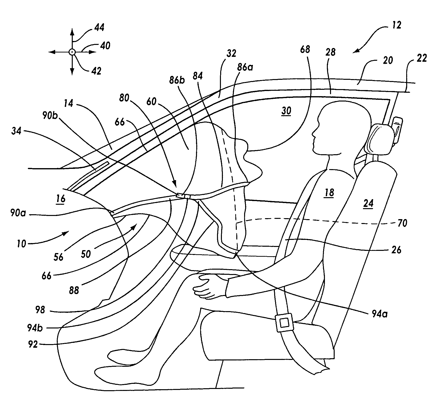
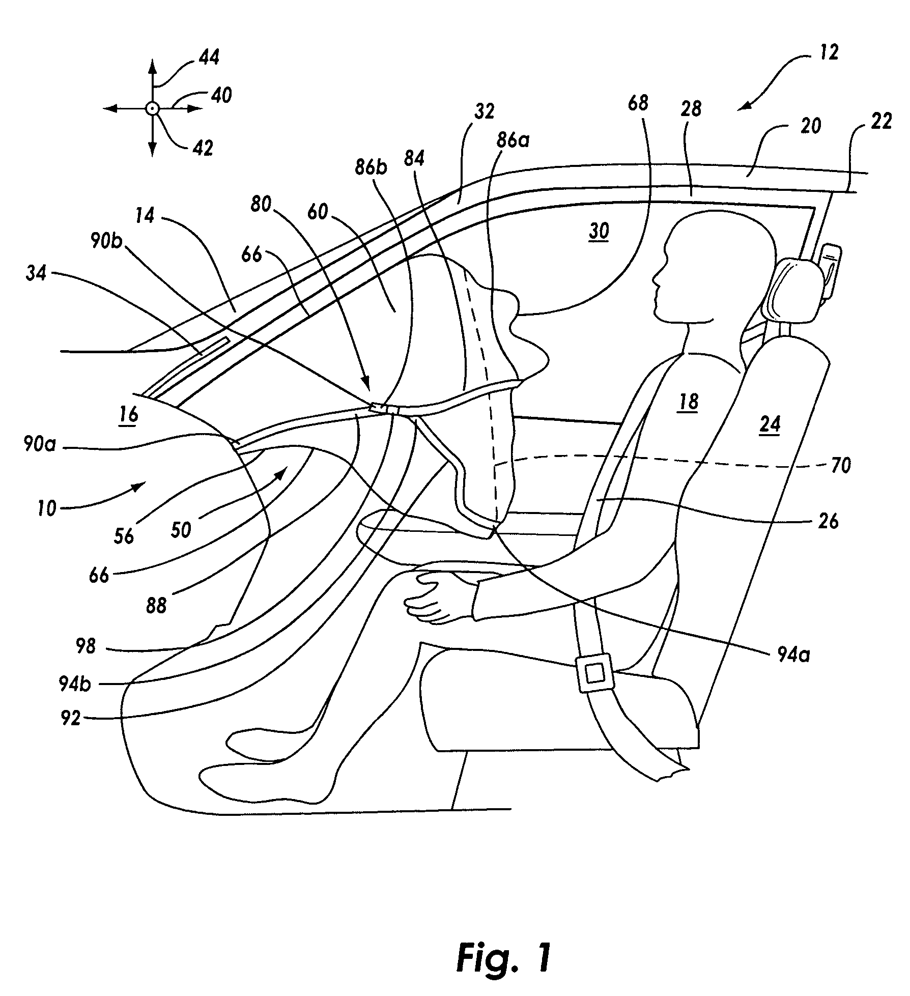
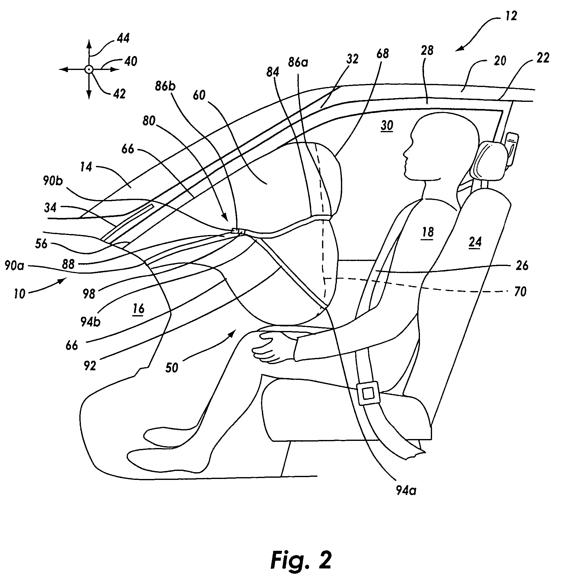
[0033]The presently preferred embodiments of the present invention will be best understood by reference to the drawings, wherein like parts are designated by like numerals throughout. It will be readily understood that the components of the present invention, as generally described and illustrated in the figures herein, could be arranged and designed in a wide variety of different configurations. Thus, the following more detailed description of the embodiments of the apparatus and system of the present invention, as represented in FIGS. 1 through 6C, is not intended to limit the scope of the invention, as claimed, but is merely representative of presently preferred embodiments of the invention.

[0034]Increased consumer and regulator awareness are driving development in the field of passive restraint devices as a whole, and specifically in the field of vehicular airbags. One issue given particular attention in recent times is the issues posed by out-of-position occupants. The issues p...


PUM


Abstract

The application provides airbag cushion deployment restraint systems for use in inflatable airbag cushions. The deployment restraint systems of the invention regulate deployment of an airbag cushion to provide full radial expansion of the cushion prior to final expansion of the cushion toward a vehicle occupant. The deployment restraint systems of the invention thus increase the amount of contact surface area available to a vehicle occupant early in deployment and decrease the force with which the cushion is expanded toward a vehicle occupant during a collision event, thus reducing the likelihood of injury to an out-of-position vehicle occupant.

Description

BACKGROUND OF THE INVENTION[0001]1. Field of the Invention[0002]The present invention relates to apparatus for regulating the deployment characteristics of an airbag cushion. More specifically, the present invention relates to apparatus and methods of their use for temporarily restraining the longitudinal expansion of a deploying airbag cushion to allow the cushion to achieve its fullest transverse width prior to expanding toward a vehicle occupant such as an out-of-position occupant.[0003]2. Description of Related Art[0004]Safety belts are designed to protect the occupants of a vehicle during events such as automobile collisions. In low-speed collisions, the occupants are generally protected from impact with objects located inside the vehicle such as the windshield, the instrument panel, a door, the side windows, or the steering wheel by the action of the safety belt. In more severe collisions, however, even belted occupants may experience an impact with the car's interior. Airbag ...

Claims


Application Information

Patent Timeline
Patent Type & Authority Patents(United States)
IPC IPC(8): B60R21/16B60R21/21B60R21/233
CPCB60R21/233B60R21/2338B60R2021/23382B60R21/2342B60R21/16B60R21/0136B60R2021/01211
Inventor WILLIAMS, JEFFREY DANIELJAMISON, PATRICK D.COLEMAN, JAMES CLYDEERICKSON, JAMES D.
Owner AUTOLIV ASP INC
Why Eureka
Try Eureka