Automatic application hand brake

a hand brake and automatic technology, applied in the direction of mechanical equipment, brake systems, transportation and packaging, etc., can solve the problems of high force, shock, and high force on the hand brake mechanism, and achieve the effect of reducing time and effort, convenient use, and safe use by the operator

Inactive Publication Date: 2003-04-24
WABTEC HLDG CORP
View PDF2 Cites 12 Cited by
  • Summary
  • Abstract
  • Description
  • Claims
  • Application Information

AI Technical Summary

Benefits of technology

0019] Another object of the present invention is to provide an apparatus engageable with a hand brake assembly which automatically activates and applies the brakes on a railway vehicle which eliminates the need of an operator to manually wind the chain on such hand brake.
0020] Yet another object of the present invention is to provide an apparatus engageable with a hand brake assembly which will significantly reduce the time and effort required by an operator to apply such hand brake by virtue of the fact that the means used to initiate an application of the hand brake is rather simple and relatively easy to use.
0021] Still another object of the present invention is to provide an apparatus engageable with a hand brake assembly which enables the apparatus to be used by an operator of basically any physical size or stature.
0022] A further object of the present invention is to provide an apparatus engageable with a hand brake assembly that is safer to use by an operator by eliminating the need to manually wind the chain on such hand brake that could cause unnecessary physical strain on the operator thus greatly reducing the chance for injury.
0023] An even further object of the present invention is to provide an apparatus engageable with a hand brake assembly on a railway vehicle which will provide the necessary torque to set such hand brake properly.
0024] A still further object of the present invention is to provide an apparatus engageable with a hand brake assembly on a railway vehicle which will substantially minimize the possibility of an operator improperly setting the hand brake by not applying enough torque thereby leaving such railway vehicle somewhat free to cause serious damage and / or possible injury to railroad personnel or, on the other hand, applying to much torque thereby possibly damaging the brake rigging of such hand brake.

Problems solved by technology

The brakes may be released by disengaging the pawl from the detent wheel but this causes rapid rotation of the hand wheel and the gears of the gear train.
This results in the gears and other components being subjected to high forces and to shock, particularly, when the chain becomes fully let-out from the chain drum.
In recent times, the AAR has added a life cycle test to its specifications, and hand brake mechanisms which do not meet the life cycle test cannot be sold for use on railway cars operated in interchange service on United States railroads.
When intermediate power hand brake mechanisms of the type sold prior to the adoption of the life cycle test were subjected to the life cycle test, it was found that the components thereof wore prematurely or were damaged, and it was found to be necessary to add a shock retarder, or absorber, external to the hand brake mechanism, to overcome such wear and damage.
Of course, such an external shock retarder is undesirable not only because it is external to the hand brake mechanism but also because of the additional cost and because it requires field modification of the equipment on a railway car if the intermediate power hand brake mechanism is used to replace a standard power hand brake mechanism.
High power hand brake mechanisms sold prior to the adoption of the life cycle test were similarly unable to pass the life cycle test.
Attempts were made to redesign the high power hand brake mechanism, such as by making it stronger, so that it would meet the life cycle test without the use of an external shock retarder, but the attempts were not successful.

Method used


Image

  • Automatic application hand brake
  • Automatic application hand brake
  • Automatic application hand brake

Examples


Embodiment Construction

[0039] Prior to proceeding to the more detailed description of the various embodiments of the present invention, for the sake of clarity and understanding of such invention, it should be noted that identical components having identical functions have been identified with identical reference numerals throughout each of the figures illustrated herein.

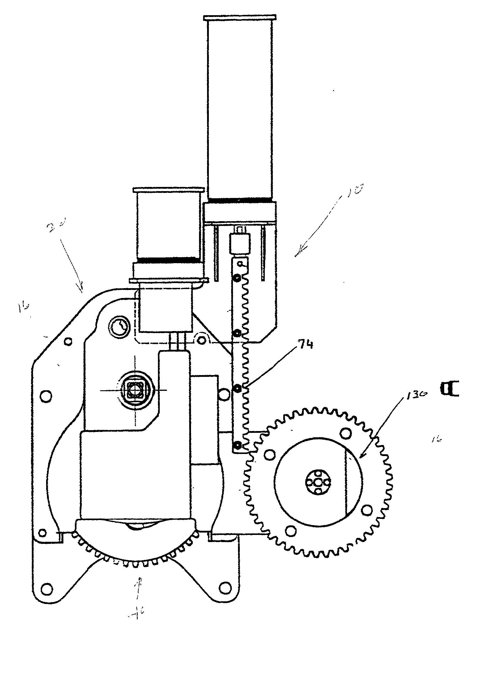
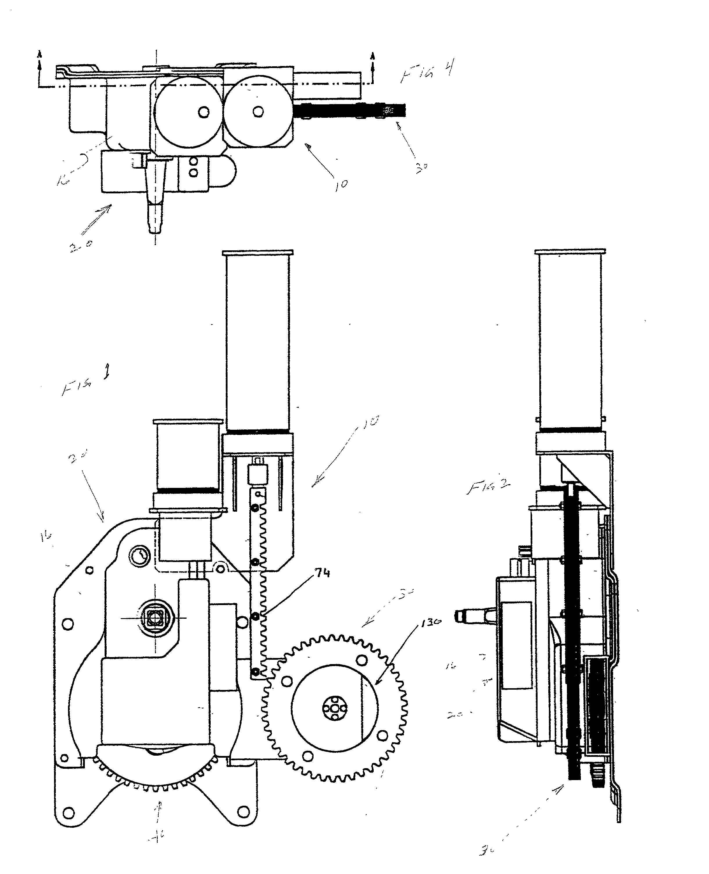
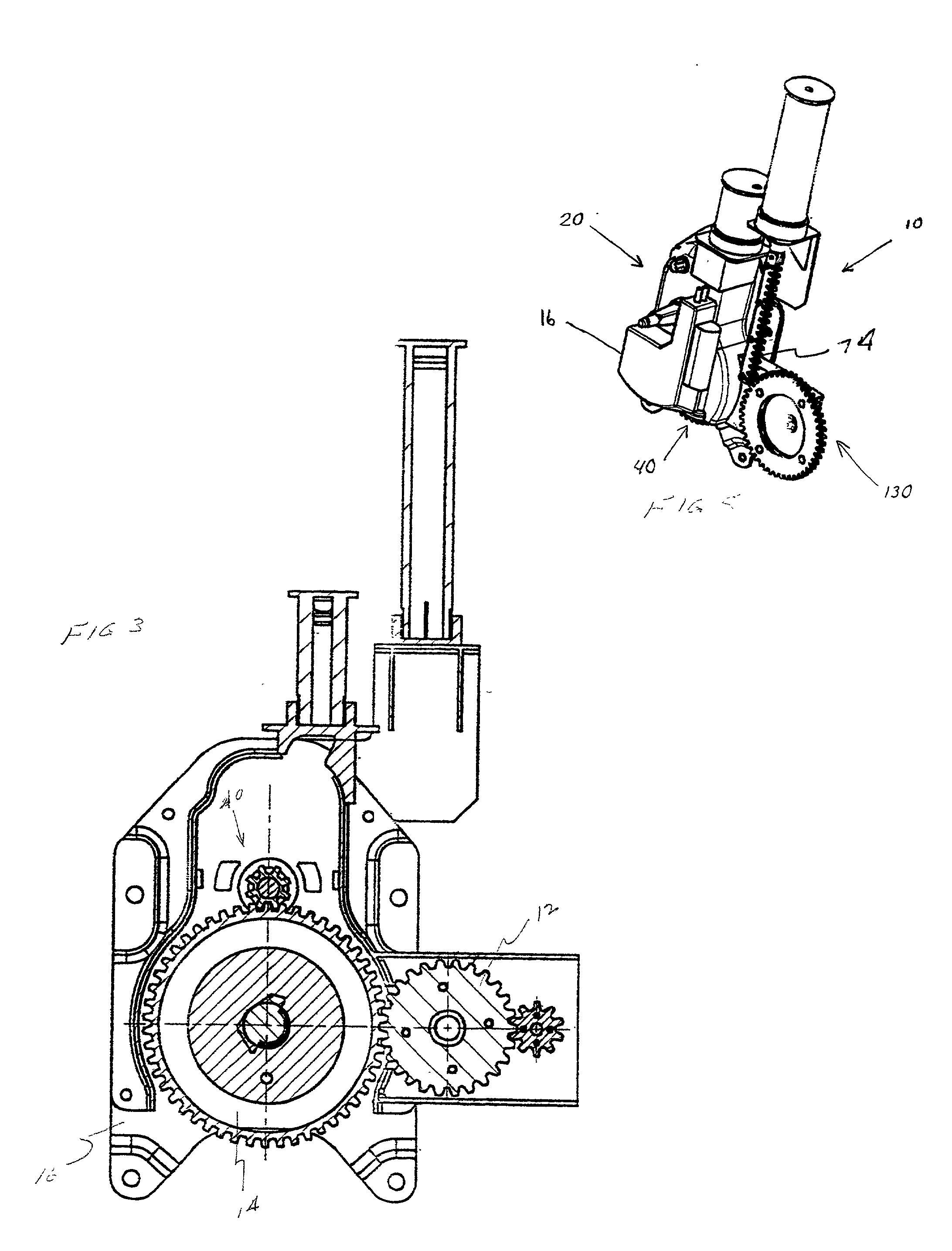
[0040] Refer now, more particularly, to FIGS. 1 through 6 of the drawings. Illustrated therein is an apparatus, generally designated 10, which is engageable with a hand brake assembly, generally designated 20, for automatically applying at least one brake means (not shown) secured to a railway vehicle (not shown) with such hand brake assembly 20.

[0041] Such apparatus 10 includes an operating means, generally designated 30. Operating means 30 has at least a portion thereof, i.e., gear 12, engageable with at least one gear 14 of a hand brake gear assembly, generally designated 40, disposed in a housing member 16 of such hand brake assembly ...


PUM


Abstract

An apparatus engageable with a hand brake assembly for automatically applying at least one brake device secured to a railway vehicle with such hand brake assembly. The apparatus includes an operating mechanism having at least a portion thereof engageable with at least one gear of a gear assembly disposed in a housing member of the hand brake assembly for operating such gear assembly in a direction which will cause an application of such brake device. A source of fluid pressure is connected to the operating mechanism for periodically supplying a predetermined pressure to such operating mechanism for the application of the brake device. An activating device is connected to the source of fluid pressure for initiating the supply of such predetermined pressure to the operating mechanism thereby causing an automatic application of such brake device by the hand brake assembly.

Description

[0001] The present invention relates, in general, to hand brake assemblies for use on railway type vehicles and, more particularly, this invention relates to an apparatus to automatically activate and apply the brakes on such railway vehicle without requiring an operator to manually wind the chain on such hand brake.[0002] Prior to the conception and development of the present invention, railway car hand brake mechanisms were well known in the art. They usually include a large, rotatable hand wheel disposed in a vertical plane and mounted on a shaft which, through a gear train, can rotate a chain drum to wind up a chain that is secured at its end remote from the chain drum to the brake rigging of the railway car. As the hand wheel is rotated in one direction, the brakes are applied and rotation of the hand wheel shaft in the opposite direction is prevented by a pawl which engages a detent wheel on the hand wheel shaft.[0003] The brakes may be released by disengaging the pawl from th...

Claims


Application Information

Patent Timeline
Patent Type & Authority Applications(United States)
IPC IPC(8): B60T7/02B61H13/20B60T7/08B61H13/02B61H13/04
CPCB60T7/08B61H13/04B61H13/02
Inventor RING, MICHAEL E.NATSCHKE, SCOTT L.
Owner WABTEC HLDG CORP
Why Eureka
Try Eureka