Articulated nozzle closure for fluid dispensers

a technology of fluid dispensers and nozzles, which is applied in the direction of liquid transferring devices, packaging goods types, liquid handling, etc., can solve the problems of reducing the accuracy affecting the operation of the dispensing system, so as to reduce the chance of injury to the operator and compact the design

Inactive Publication Date: 2007-08-28
FLUID MANAGEMENT LLC
View PDF59 Cites 12 Cited by
  • Summary
  • Abstract
  • Description
  • Claims
  • Application Information

AI Technical Summary

Benefits of technology

[0011]In another refinement, a biasing mechanism is also included which biases the hub and closure to a position where the closure is disposed beneath the nozzle or manifold. Rotation of the threaded shaft which initially results in downward movement of the hub and closure also works against the bias of the biasing mechanism when the finger or stud engages the abutment, the hub is rotated against the bias of the biasing element to pivot the closure away from the nozzle or manifold. After the fluid is dispensed, the biasing element moves the hub and closure back to a position where the closure is disposed immediately below the nozzle or manifold. Then, a reverse action of the motor spins the shaft in an opposite direction thereby returning the hub and closure upward to its closed and sealed position. The use of a biasing element to rotate the closure element back into place reduces the chance of injury to the operator during the initial movement to the closed position.
[0012]In a refinement, the curved slot extends about the common axis for a limited range extended from about 30 to about 60° and preferably about 45°. This limits the pivoting movement of the closure away from the nozzle thereby providing for a relatively compact design. Because of the limited pivotal motion of the closure element, an optional cover may be provided on the underside of the system for safety and cleanliness.
[0015]In another refinement, the motor is a one-way motor thereby allowing the system to rely upon the biasing mechanism to return the closure from its open and unsealed position back to its closed and sealed position after the dispensing operation is completed.
[0019]In another refinement, one or more light emitting devices such as light emitting diodes (LEDs) may be included for assisting the operator to properly place the container below the nozzle or manifold. Preferably, the light emitters are disposed on an underside of the cup or closure or on an underside of the arm connecting the cup or closure to the hub. The light emitters may also be disposed along the outer side of any support structure or on the hub itself. If the light emitters are disposed on the underside of the arm connecting the closure to the hub or on the underside of the hub, the light emitters are pivoted out of the way when the fluid is dispensed, and are therefore protected against splashing or being coated with fluid material which would limit or impede there effectiveness.
[0021]In another refinement, the distal end of the threaded shaft is connected to a retainer element. The retainer element serves to keep the biasing element (preferably a spring) in place and provides an easy means for attaching the finger or stud which engages the abutment for purposes of rotating the hub and closure element out of the way of a nozzle or manifold.

Problems solved by technology

One way in which the precision of dispensing systems is compromised is “dripping.” Specifically, a “leftover” drip may be hanging from a nozzle that was intended to be added to a previous formulation and, with a new container in place under the nozzle, the drop of liquid intended for a previous formulation may be erroneously added to a new formulation.
Thus, the previous container may not receive the desired amount of the liquid ingredient and the next container may receive too much.
However, these designs often require one or more different motors to operate the wiper element and are limited to use on dispensing systems where the nozzles are separated or not bundled together in a manifold.
Use of a wiper or scraping function would not be practical in a multiple nozzle manifold design as the ingredients from the different nozzles will be co-mingled by the wiper or scraper which would then also contribute to the lack of precision of subsequently produced formulations.
Another problem associated with dispensing systems that make use of nozzles lies in the dispensing of relatively viscous liquids such as tints, colorants, base materials for cosmetic products, certain pharmaceutical ingredients or other fluid materials having relatively high viscosities.
While some mechanical wiping or scrapping devices are available, these devices are not practical for multiple nozzle manifold systems and the scraper or wiper element must be manually cleaned anyway.
To date, applicants are not aware of any attempts to provide any sort of nozzle or manifold closure or sealing element that would protect against drips as well as reducing the frequency in which the nozzle or manifolds must be cleaned.

Method used


Image

  • Articulated nozzle closure for fluid dispensers
  • Articulated nozzle closure for fluid dispensers
  • Articulated nozzle closure for fluid dispensers

Examples


Embodiment Construction

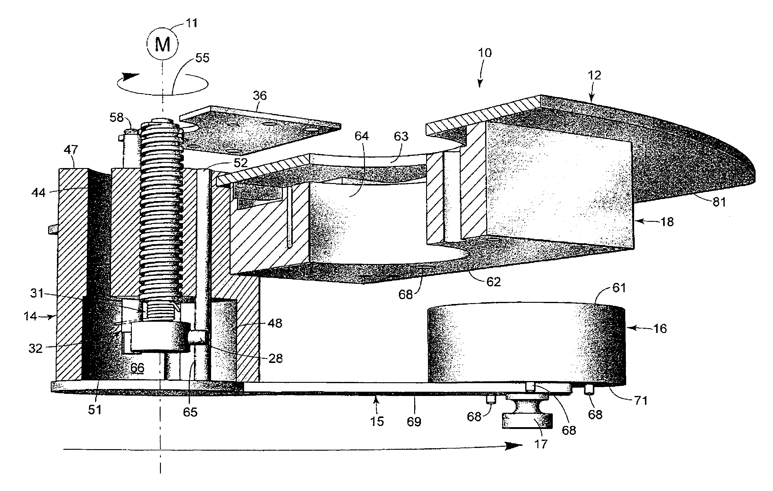
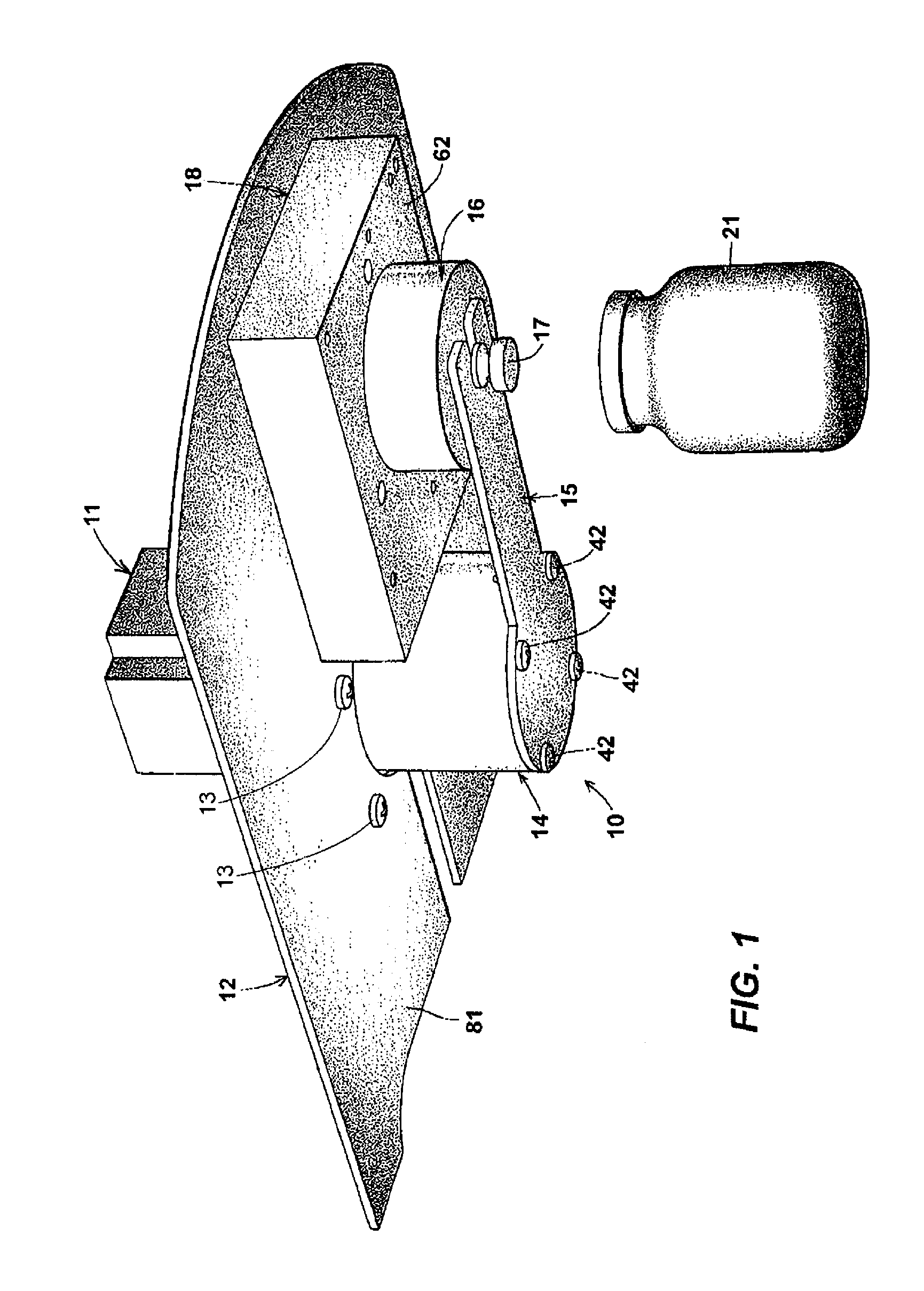
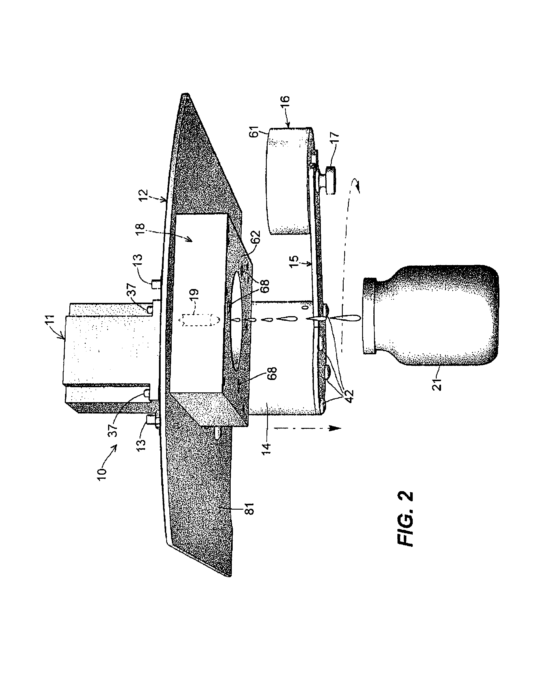
[0034]Turning to FIG. 1, a closure system 10 is disclosed which includes a motor 11 supported by a mounting plate 12. The motor 11 is connected to the mounting plate by a plurality of fasteners shown at 13. The motor 11 is coupled to a hub 14 which, in turn, is connected to an arm 15 which connects the hub 14 to a closure element 16 which, in the embodiment shown, is a cup-shaped structure. A fastener 17 is used to connect the arm 15 to the closure element 16. It would be noted that the hub structure 14 could be altered so that it is connected directly to the closure element 16. As shown in the position of FIG. 1, the closure element 16 engages the underside of a block 18 which surrounds one or more nozzles 19 (see FIG. 2). A container 21 is disposed below and in general alignment with the nozzle 19 and block 18.

[0035]In the position shown in FIG. 1, the closure system 10 is in a closed or sealed position with the closure element 16 engaging the block 18. Turning to FIG. 2, the syst...


PUM

PropertyMeasurementUnit
sizeaaaaaaaaaa
flexibleaaaaaaaaaa
coloraaaaaaaaaa

Abstract

A closure system for a fluid outlet is disclosed which includes a motor threadably connected to a hub which, in turn, is connected to a closure element or cup that provides a sealing cover beneath one or more nozzles. The action of the motor initially lowers the closure element vertically before pivoting the closure element away from the area directly beneath the nozzle or nozzles. After fluid is dispensed, a biasing element pivots the closure element back into place before it is raised vertically again to provide a seal or cover for the one or more nozzles. The hub is designed to pivot only a partial revolution and the pivoting action of the hub and closure element away from the nozzle area overcomes the bias of the biasing element contained within the hub. The biasing element then pivots the hub and closure element back into place before the biasing element raises the hub and closure element to its original position.

Description

TECHNICAL FIELD[0001]An improved closure system for fluid dispensers is shown and described. The disclosed closure system is a motorized, articulated system that, in a closed position, provides a cover or closure for a nozzle or nozzle manifold through which one or more fluids are dispensed. In the closed position, the closure element is disposed beneath the nozzle or nozzle manifold and collects any fluid drippings between dispensing operations and also preferably provides a sealing effect. To move the closure system to an open or to a dispense position, a motor is activated which moves the closure element downward before pivoting the closure element away from the nozzle or nozzle manifold. After the fluid is dispensed, a biasing element pivots the closure element back in place with little risk of injury to the operator. An underside of the closure element or the support structure for the system may also include one or more light emitting devices to help the operator put the contai...

Claims


Application Information

Patent Timeline
Patent Type & Authority Patents(United States)
IPC IPC(8): B65B1/30B67D3/00B65B3/36B65B39/00
CPCB65B3/36B65B39/005B67D1/0887B67D1/1256B05B15/50
Inventor CLEVELAND, JAMES R.HOGAN, TIM
Owner FLUID MANAGEMENT LLC
Why Eureka
Try Eureka