

Dismountable skeleton tool, and dismounting device and method for same
A tooling and skeleton technology, applied in the field of detachable skeleton tooling and its disassembly device and method, achieves the effects of reducing the difficulty of disassembly, uniform and controllable force, and reducing the probability of damage
- Summary
- Abstract
- Description
- Claims
- Application Information
AI Technical Summary
Problems solved by technology
Method used
Image

Examples
Embodiment Construction
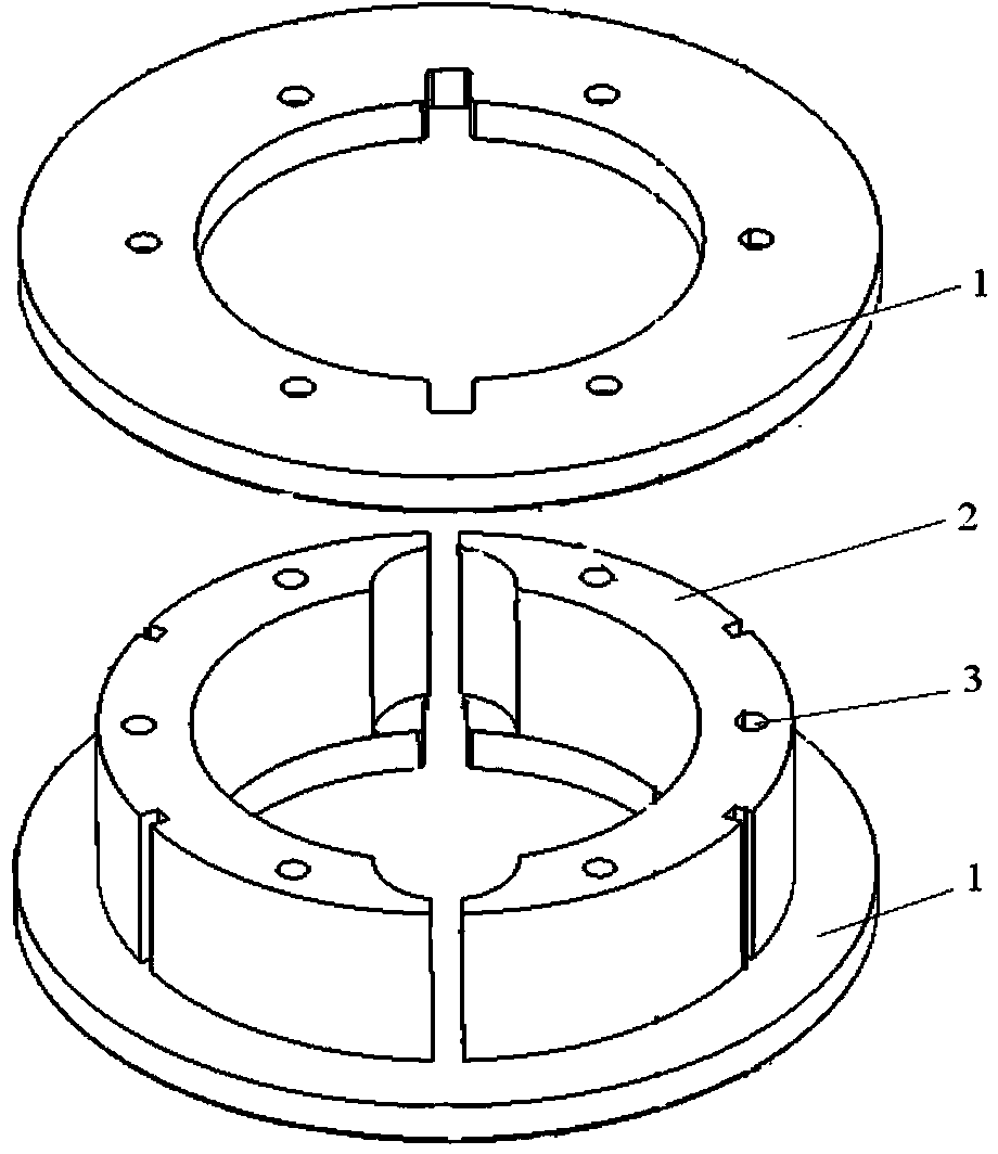
[0035] Such as figure 1 As shown, a detachable skeleton tooling of the present invention includes a cover piece 1, a hub 2, and a screw 3; the cover piece 1 is a circular structure; There is a gap between the circular hollow cylindrical shells; the two covers 1 are fixedly connected to the axial end faces on both sides of the hub 2 through screws 3; a set of grooves are symmetrically dug in the diameter direction of the inner ring of the two covers 1.
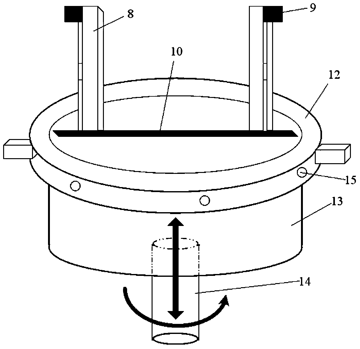
[0036] Such as figure 2 As shown, a dismounting device of a detachable skeleton tooling of the present invention includes a slidable fixed column 8, a slidable card 9, a fixed platform 12, a rotating lifting cylinder 13, a bearing 14 and a motor 15; the rotating and lifting cylinder 13 is a solid Cylindrical structure; the bearing 14 is fixedly connected to the lower end surface of the rotating and lifting cylindrical platform 13; the upper end surface of the rotating and lifting cylindrical platform 13 is engraved with groov...
PUM
 Abstract
Description
Claims
Application Information