Supercharge Your Innovation With Domain-Expert AI Agents!

Plastic spacer and disk clamp assembly

a technology of spacer and disk, applied in the field of composite disk clamps, can solve the problems of deformation of top clamp and spacer, loss of servo, data loss,

Inactive Publication Date: 2007-03-27
WESTERN DIGITAL TECH INC
View PDF9 Cites 6 Cited by
  • Summary
  • Abstract
  • Description
  • Claims
  • Application Information

AI Technical Summary

Problems solved by technology

Great pressure must be exerted by the bolts on the top clamp in order to prevent slippage of the disks in the event that the drive is bumped or uneven thermal expansion that breaks the frictional coupling, because once the disks slip, the drive loses its servo and the data is lost.
A major drawback of the current practice is that when the bolts are tightened, the top clamp and spacer become deformed due to the uneven pressures exerted by the individual bolts.
Another issue encountered in the prior art is the high cost of assembling the drives.
This process is time consuming.

Method used


Image

  • Plastic spacer and disk clamp assembly
  • Plastic spacer and disk clamp assembly
  • Plastic spacer and disk clamp assembly

Examples


Embodiment Construction

[0029]The following description is the best embodiment presently contemplated for carrying out the present invention. This description is made for the purpose of illustrating the general principles of the present invention and is not meant to limit the inventive concepts claimed herein.

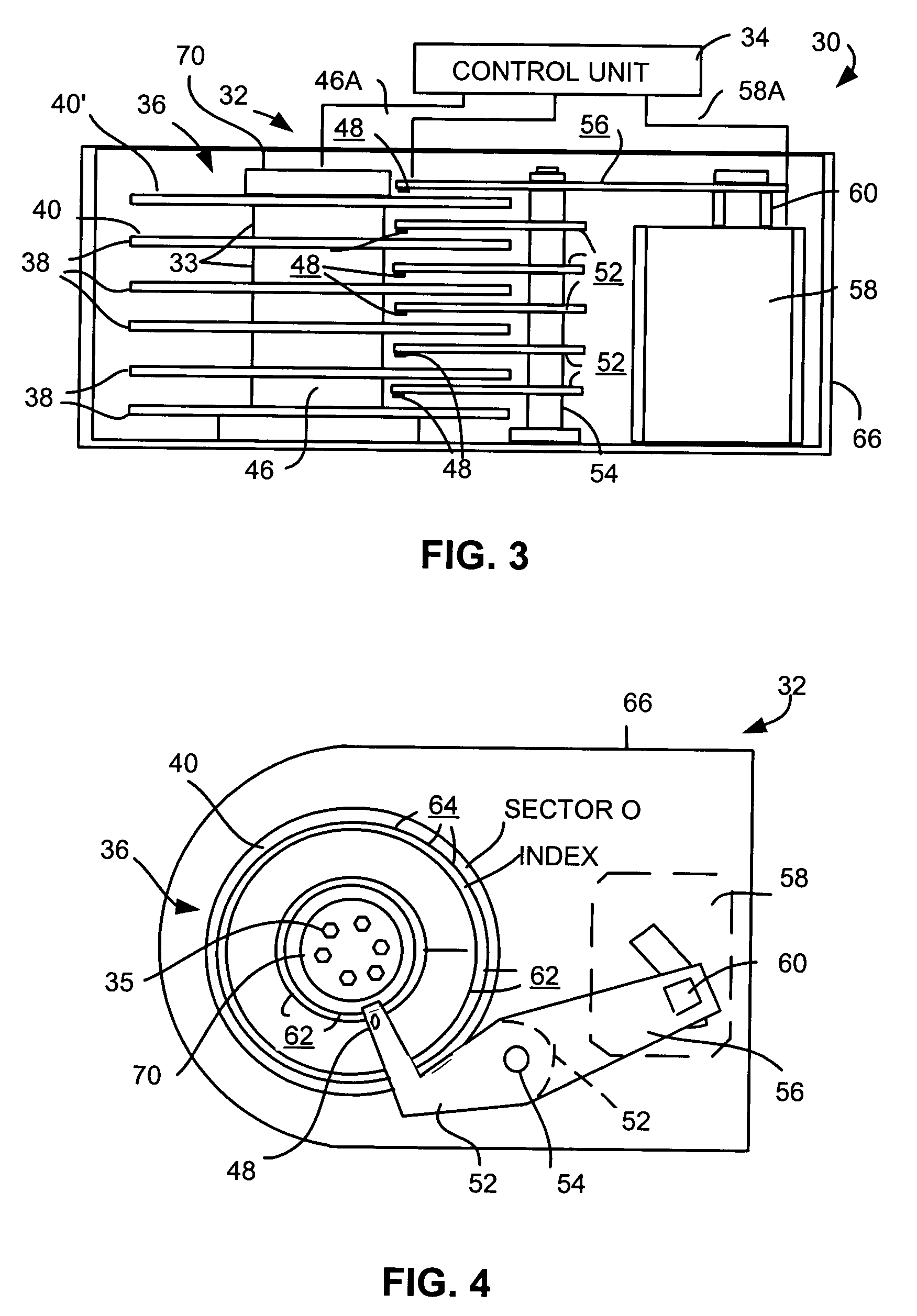
[0030]Referring now to the drawings wherein like reference numerals designate like or similar parts throughout the several views there is illustrated in FIG. 3 a cross-sectional diagram of parts of a data storage disk drive system 30 including a rigid magnetic disk drive unit generally designated as 32 and a control unit generally designated as 34. While a magnetic disk drive unit is illustrated, it should be understood that other mechanically moving memory configurations may be used. Unit 32 is illustrated in simplified form sufficient for an understanding of the present invention because the utility of the present invention is not limited to the details of a particular drive unit construction. After...


PUM

PropertyMeasurementUnit
hardnessaaaaaaaaaa

Abstract

An assembly for coupling a disk to a spindle includes an annular spacer ring adapted to engage the disk and an annular clamp. The spacer ring is constructed at least in part of a plastic material. The clamp is constructed of a material having a modulus and stiffness greater than that of the spacer ring.

Description

FIELD OF THE INVENTION[0001]The present invention relates to disk drive components, and more particularly, this invention relates to a composite disk clamp that provides high rigidity and integral material matching at the disk-clamp interface.BACKGROUND OF THE INVENTION[0002]A typical disk drive storage system includes one or more magnetic disks which are mounted for co-rotation on a hub or spindle. A typical disk drive also includes a transducer supported by a hydrodynamic bearing which flies above each magnetic disk. The transducer and the hydrodynamic bearing are sometimes collectively referred to as a data head or a product head. A drive controller is conventionally used for controlling the disk drive based on commands received from a host system. The drive controller controls the disk drive to retrieve information from the magnetic disks and to store information on the magnetic disks. An electromechanical actuator operates within a negative feedback, closed-loop servo system to...

Claims


Application Information

Patent Timeline
Patent Type & Authority Patents(United States)
IPC IPC(8): G11B17/02G11B17/038
CPCG11B17/038
Inventor FELISS, NORBERT A.GILLIS, DONALD RAYWOLTER, REINHARD F.
Owner WESTERN DIGITAL TECH INC
Features
  • R&D
  • Intellectual Property
  • Life Sciences
  • Materials
  • Tech Scout
  • Unparalleled Data Quality
  • Higher Quality Content
  • 60% Fewer Hallucinations
Learn More