Supplied air helmet having face seal with differentiated permeability

a technology of face seal and air helmet, which is applied in the direction of eye treatment, lighting and heating apparatus, heating types, etc., can solve the problems of not being able to fully optimize the air flow of known products within the supplied air helmet, and the product has not been fashioned to enable air to be purged in a differentiated manner. , to achieve the effect of reducing the amount of contaminants

Inactive Publication Date: 2007-04-03
3M INNOVATIVE PROPERTIES CO
View PDF43 Cites 52 Cited by
  • Summary
  • Abstract
  • Description
  • Claims
  • Application Information

AI Technical Summary

Benefits of technology

[0007]The inventive supplied air helmet is beneficial in that use of a face seal with differentiated permeability may provide a controlled flow of air within the interior gas space. Airflow can be managed, for example, to allow it to flow from an inlet port located at the wearer's forehead, across the front of the wearer's face, and then exit the interior gas space beneath the chin. Air that exits the interior gas space can readily enter the exterior gas space to allow room for new clean air to be furnished to the breathing zone. The managed airflow may provide a comfortable environment to the wearer and may also provide less opportunity for the wearer to inhale contaminants that may be present in the ambient environment or exterior gas space.
[0016]“face seal” means a structure that contacts a person's face to help separate an interior gas space of a supplied air helmet from an exterior gas space;
[0017]“filtered air” means air that has been passed through a filter material to reduce the amount of any contaminants that may have been present in the air before it was filtered;
[0024]“permeability” means the ability of a gaseous fluid to pass therethrough (media that has a greater permeability allows the gaseous fluid to pass therethrough more easily (i.e., with less pressure drop or greater airflow rate));

Problems solved by technology

While known face seal products have provided a variety of constructions for establishing a boundary between the interior gas space and the surrounding environment, these known products have not been fashioned to enable air to be purged from the mask interior in a differentiated manner.
The known products thus may not have fully optimized air flow within the supplied air helmet to improve comfort and to preclude air inflow from the surrounding environment.

Method used


Image

  • Supplied air helmet having face seal with differentiated permeability
  • Supplied air helmet having face seal with differentiated permeability
  • Supplied air helmet having face seal with differentiated permeability

Examples


example

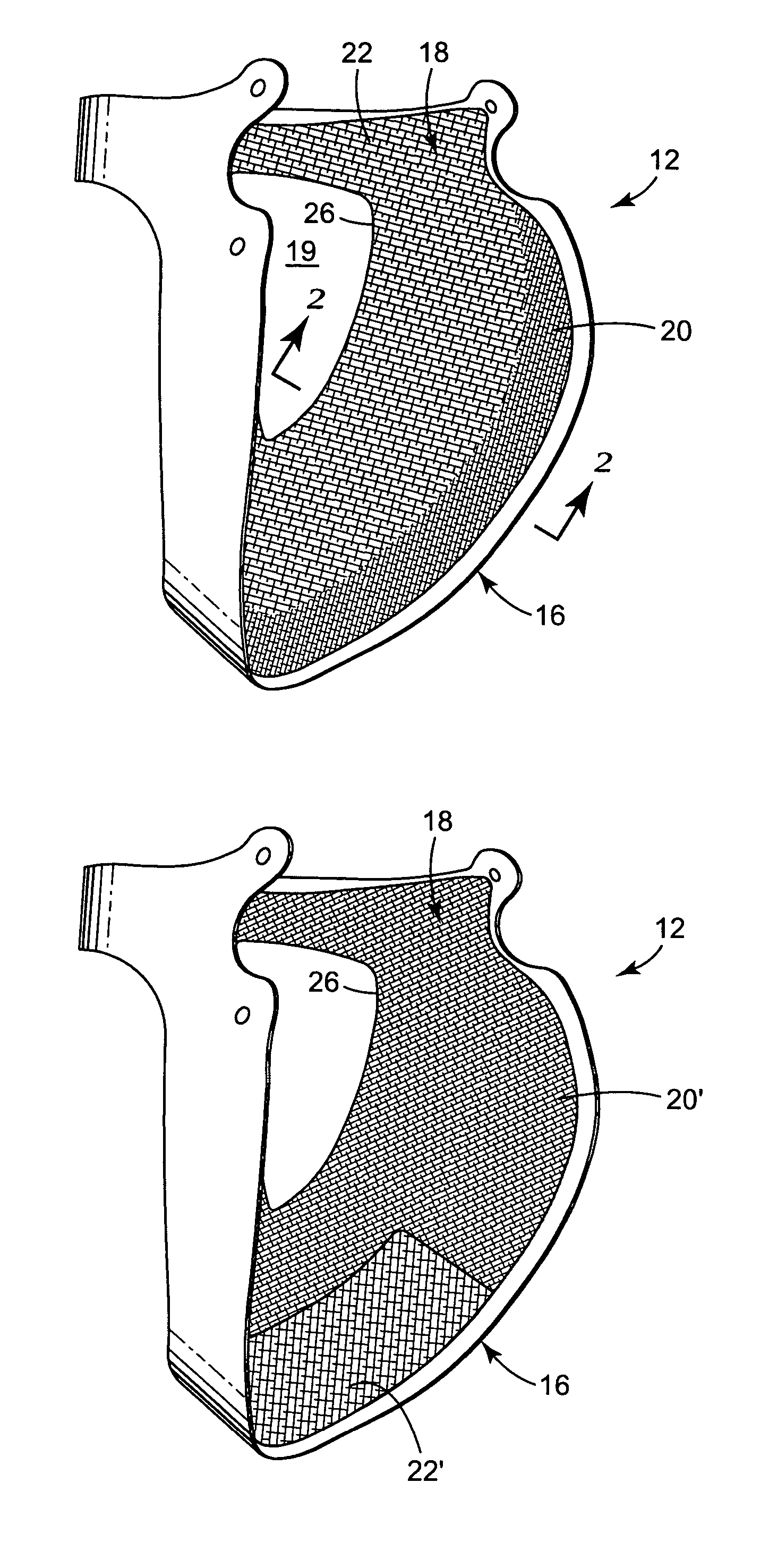
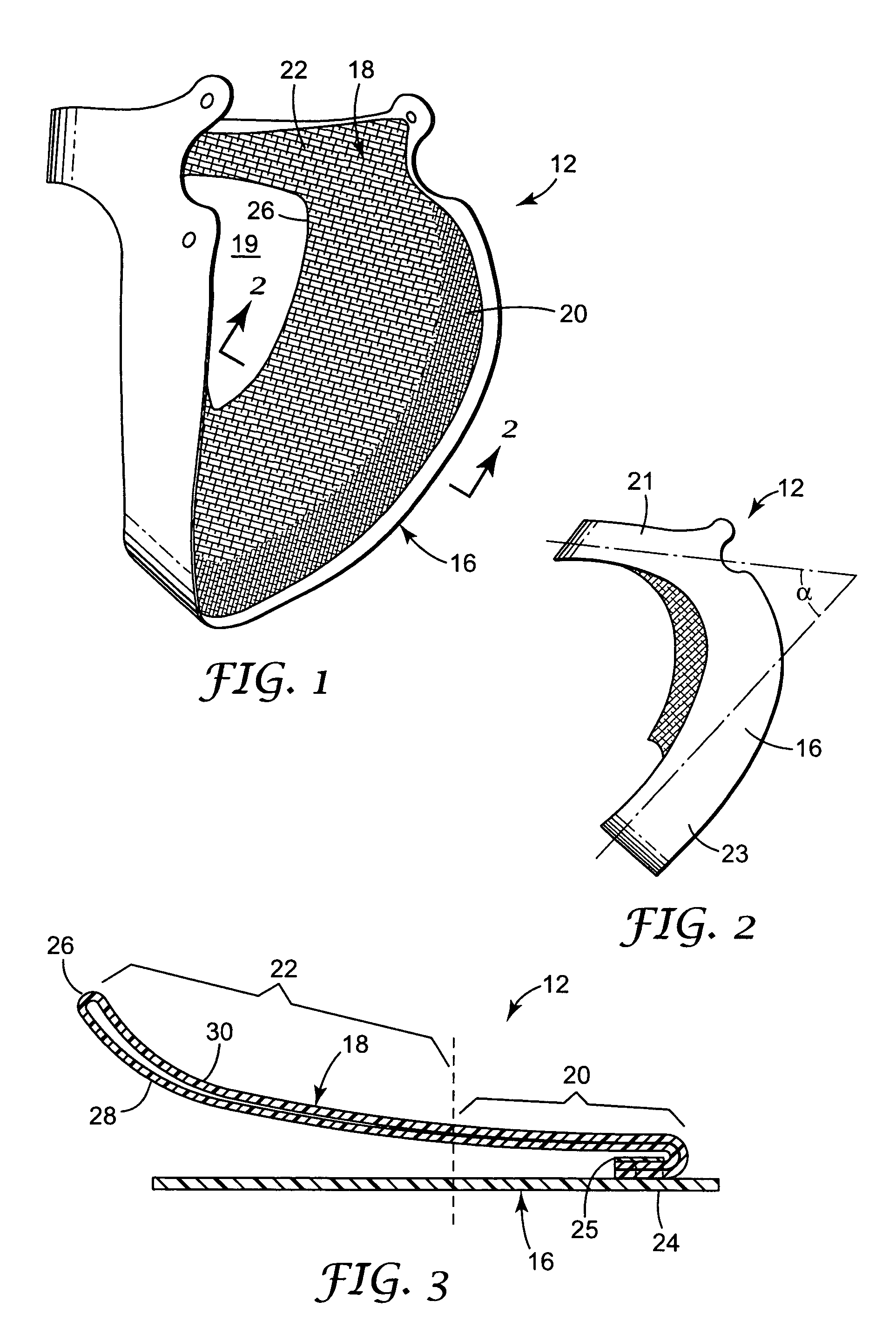
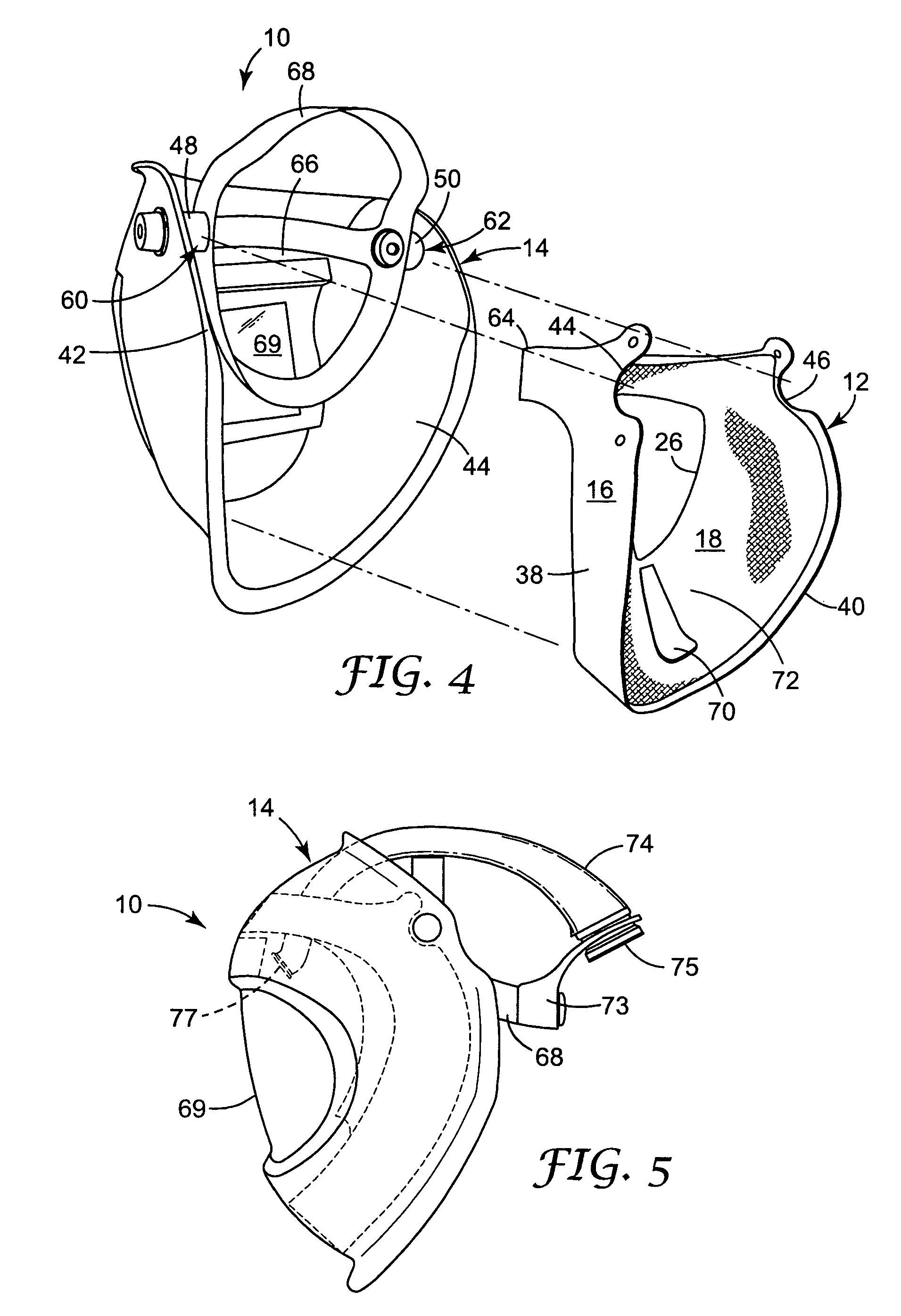
[0069]The face seal sealing member was made from a rectilinear 1& 1 rib knitted blank that had been cut and sewn to achieve the desired shape and configuration. The blank was made from three yarns: a combined flame-retardant / comfort yarn, an elastic yarn, and a water soluble yarn. The combined flame-retardant / comfort yarn contained Kanecaron™ fiber, Protex-M, (a modified acrylic available from the Kaneka Corporation, Japan) and cotton fiber. Relative to each other, the Kanecaron™ fiber was used at 55 weight %, and the cotton fiber was used at 45 weight %. The elastomeric yarn was 200 decitex and contained an elastane, Lycra™, and crimped nylon at 62 wt. % and 38 wt. %, respectively. These two yarns functioned as the primary structural element in the knitted blank. The combined flame-retardant / cotton yarn and the elastic yarn were both dyed blue. The flame-retardant / comfort yarn was waxed as well. Content of elastic yarn in the blank varied along the length of the blank with the high...


PUM


Abstract

A supplied air helmet 10 comprises a visor 14 and a face seal 12 that is secured to the visor. The face seal 12 includes a sealing member 18 and a frame member 16. The sealing member 18 extends radially inward from the frame member 16 and has first and second regions of permeability 20 and 22. The second region 22 has greater permeability than the first region 20. The use of a face seal 12 that has differentiated permeability allows for a controlled flow of air through the interior of the supplied air helmet 10.

Description

[0001]The present invention pertains to a supplied air helmet that has a face seal that exhibits differentiated airflow permeability in at least two different zones.BACKGROUND[0002]Supplied air helmets are regularly worn in environments where the surrounding air contains contaminants. These helmets have a fluid impermeable visor that is located in front of the wearer's face when the helmet is worn. The visor has a window that allows the wearer to see the surrounding environment. A face seal is attached to the visor to separate a breathing zone or an interior gas space from the surrounding exterior gas space. The interior gas space is located between the visor and the wearer's face and is defined, for the most part, by the face seal that is attached to the visor, the visor body, and the wearer's face. U.S. Pat. Nos. 6,014,971, 4,462,399, and 4,280,491 disclose examples of supplied air helmets that use face seals for this purpose.[0003]Clean air is forced into the interior gas space f...

Claims


Application Information

Patent Timeline
Patent Type & Authority Patents(United States)
IPC IPC(8): A61F9/02A62B18/08
CPCA61F9/045A62B18/04A61F9/068A42B3/286
Inventor CURRAN, DESMOND T.LEE, PETER D.WILLIAMS, RICHARD D.YATES, PETER N.BAKER, DEREK S.
Owner 3M INNOVATIVE PROPERTIES CO
Why Eureka
Try Eureka