
Source-injection parallel coupled LC-quadrature voltage controlled oscillator

a voltage control and source-injection technology, applied in the direction of oscillator generators, pulse generation by logic circuits, pulse techniques, etc., can solve the problems of increasing the phase noise, deteriorating the phase noise, and generating low-frequency noise, so as to eliminate the low-frequency noise

Inactive Publication Date: 2007-04-03
INFORMATION & COMM UNIV RES & INDAL COOPERATION GROUP
View PDF11 Cites 18 Cited by
  • Summary
  • Abstract
  • Description
  • Claims
  • Application Information

AI Technical Summary

Benefits of technology

[0023]It is an advantage of the present invention to provide a quadrature voltage controlled oscillator for eliminating low-frequency noise from a coupling transistor.
[0024]It is another advantage of the present invention to provide a quadrature voltage controlled oscillator operable at a low supply voltage.
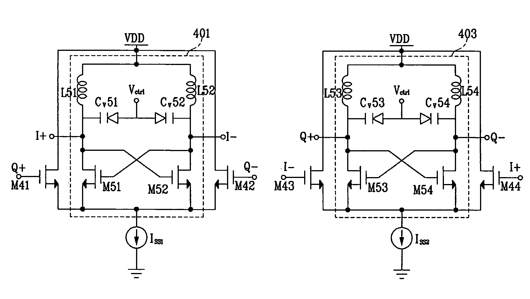
[0025]In one aspect of the present invention, provided is a quadrature VCO comprising a first delay cell for outputting a first in-phase signal and a second in-phase signal with different phases, and a second delay cell for outputting a first quadrature-phase signal and a second quadrature-phase signal with different phases.
[0026]The first delay cell comprises: a first differential VCO coupled between a power supply and a first current source; and a first coupling transistor and a second coupling transistor that each includes a first terminal, a second terminal coupled to the power supply, and a third terminal, the first and second coupling transistors varying a magnitude and a direction of a current which flows from the second terminal to the third terminal according to magnitudes of the first and second quadrature-phase signals respectively applied to the first terminal.
[0027]The second delay cell comprises: a second differential VCO coupled between a power supply and a second current source; and a third coupling transistor and a fourth coupling transistor including a first terminal, a second terminal coupled to the power supply, and a third terminal, the third and fourth coupling transistors varying a magnitude and a direction of a current which flows from the second terminal to the third terminal according to magnitudes of the second and first in-phase signals respectively applied to the first terminal.
[0028]In one embodiment, the third terminals of the first and second coupling transistors are coupled to the first current source, and the third terminals of the third and fourth coupling transistors are coupled to the second current source.

Problems solved by technology

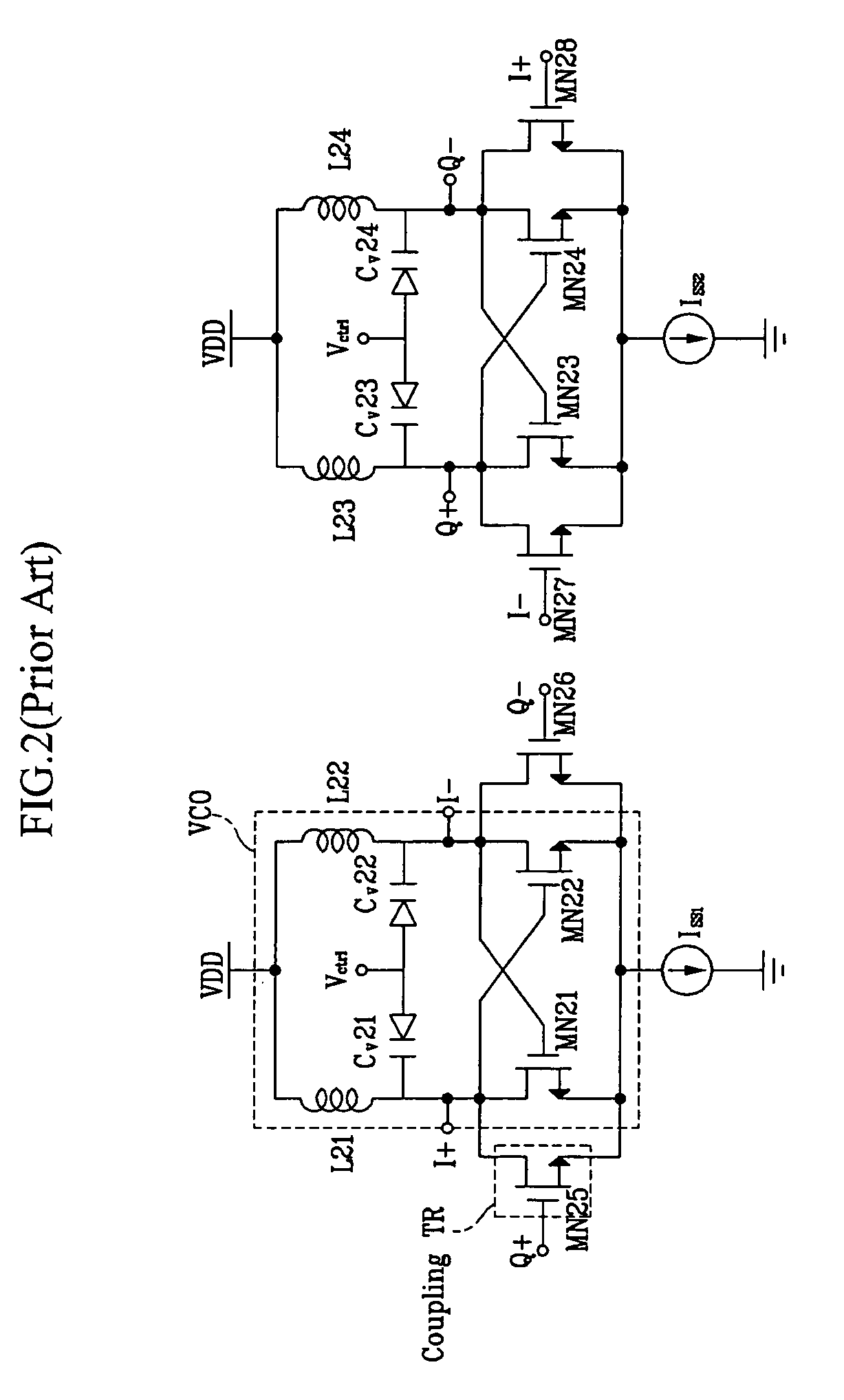
The conventional quadrature VCO shown in FIG. 2 outputs four kinds of signals with the same magnitude but different phases through a relatively easy method, but it has a problem in that low-frequency noise generated by the fifth to eighth NMOS transistors MN25 to MN28 is directly induced to the inductor of the LC tank and the frequency is accordingly transited.
This problem deteriorates a phase noise characteristic of the quadrature VCO and increases more phase noise than the phase noise characteristic of the differential VCO.

Method used


Image

  • Source-injection parallel coupled LC-quadrature voltage controlled oscillator
  • Source-injection parallel coupled LC-quadrature voltage controlled oscillator
  • Source-injection parallel coupled LC-quadrature voltage controlled oscillator

Examples


Embodiment Construction

[0042]In the following detailed description, only the preferred embodiment of the invention has been shown and described, simply by way of illustration of the best mode contemplated by the inventor(s) of carrying out the invention. As will be realized, the invention is capable of modification in various obvious respects, all without departing from the invention. Accordingly, the drawings and description are to be regarded as illustrative in nature, and not restrictive. To clarify the present invention, parts which are not described in the specification are omitted, and parts for which similar descriptions are provided have the same reference numerals.

[0043]The quadrature VCO (voltage controlled oscillator) according to the preferred embodiment of the present invention will be described in detail with reference to drawings.

[0044]The quadrature VCO uses eight active elements MN41 to MN44 and MN51 to MN55. Each active element MN comprises a gate, a source, and a drain. Magnitudes and d...


PUM


Abstract

A quadrature VCO comprises: a first delay cell including a first differential VCO coupled between a power supply and a first current source; and first and second coupling transistors that each include a first terminal, a second terminal coupled to the power supply, and a third terminal, and that vary a current flowing from the second terminal to the third terminal according to quadrature-phase signals applied to the first terminal; and a second delay cell including a second differential VCO coupled between a power supply and a second current source; and third and fourth coupling transistors that each include a first terminal, a second terminal coupled to the power, and a third terminal, and that vary a current flowing from the second terminal to the third terminal according to in-phase signals applied to the first terminal.

Description

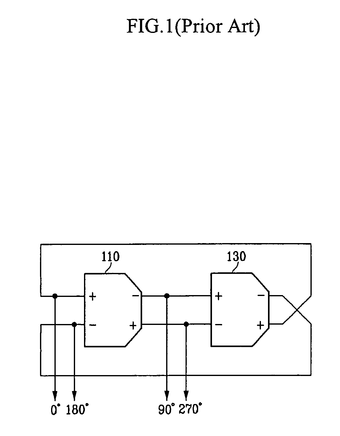
CROSS REFERENCE TO RELATED APPLICATION[0001]This application claims priority to and the benefit of Korea Patent Application No. 10-2003-0055429 filed on Aug. 11, 2003 in the Korean Intellectual Property Office, the entire content of which is incorporated herein by reference.BACKGROUND OF THE INVENTION[0002](a) Field of the Invention[0003]The present invention relates to a voltage controlled oscillator. More specifically, the present invention relates to a voltage controlled oscillator with lower power and low phase noise.[0004](b) Description of the Related Art[0005]A quadrature VCO (voltage controlled oscillator) is a circuit for generating four kinds of signals with the same magnitude but delays of 90 degrees respectively, and is generally applied to direct conversion transmitters and receivers. Direct conversion is a method for converting RF (radio frequency) signals into baseband signals without converting them into IF (intermediate frequency) signals, and is being actively deve...

Claims


Application Information

Patent Timeline
Patent Type & Authority Patents(United States)
IPC IPC(8): H03B5/12H03B27/00H03K3/03H03K3/354
CPCH03B27/00H03K3/0322H03K3/354H03B5/1228H03B5/1215H03B5/1243
Inventor LEE, SANG GUGSHIN, SO BONGCHOI, HYOUNG CHUL
Owner INFORMATION & COMM UNIV RES & INDAL COOPERATION GROUP
Learn More