Oil-immersed and high-pressure tripping switch structure

a switch structure and high-pressure technology, applied in the direction of circuit-breaking switches, circuit-breaking switches for excess current, high-tension/heavy-dress switches, etc., can solve the problems of increased accident probability, insufficient insulation distance, operation errors, etc., to increase the swinging range of operation, prevent any operation errors, and save a lot of operation.

Inactive Publication Date: 2007-04-03
JAKER ELECTRIC
View PDF5 Cites 36 Cited by
  • Summary
  • Abstract
  • Description
  • Claims
  • Application Information

AI Technical Summary

Benefits of technology

[0005]It is, therefore, the primary purpose of the present invention to provide an oil-immersed and high-pressure tripping switch structure wherein a single main spring is applied and, via the displacement of a spring rebound pivoting-point, the main spring is changed in the direction of motion so as to easily achieve various mechanisms such as the switch-on, the automatic trip-off, and the indication of movement thereof. Besides, the linkage rotating rod of an operational handle and a rotary arm actuating the main spring thereof are not connected in a concentric arrangement so as to increase the swinging range thereof in operation. In addition to saving a lot of efforts in operation, the operational handle when tripped will swing in a larger range to obviously indicate the tripped / off status thereby.
[0006]It is, therefore, the second purpose of the present invention to provide an oil-immersed and high-pressure tripping switch structure wherein an automatic tripping safety device is provided to trip / off the switch in case of an oil-shortage. Besides, the tripping safety device is equipped with an anti-shock property to prevent any mistakes in operation caused by vibrations or earthquakes. The shock-resistant and oil-shortage automatic tripping safety device includes an oil-retaining tank with an upper opening, a buoyant tube coupled with the oil-retaining tank disposed on top thereof before put into a damping oil cup disposed at the bottom thereof, and a linkage rod extending from the bottom of the buoyant tube and right through the damping oil tank thereof to connect with one end of an oil-shortage tripping device thereby. The buoyant tube and the oil-retaining tank are immersed in the insulating oil without the buoyant tube floating on the oil surface. With the effect of the damping oil cup, the tripping device will almost not be shaken along in case any vibrations occur. Thus, the switch will not be mistakenly operated due to the vibrations thereof. When an oil-shortage causes the oil surface to lower down, the oil-retaining tank filled with the insulating oil will gradually emerge to the oil surface till the weight of the insulating oil stored inside the oil-retaining tank will directly activate the tripping device of the switch thereof so as to achieve an automatic tripping mechanism in case of oil-shortage thereof.
[0007]It is, therefore, the third purpose of the present invention to provide an oil-immersed and high pressure tripping switch structure wherein an arc-extinguishing cylinder is provided, utilizing a complex arc-quenching mechanism in which a spray-type arc-interrupting chamber is applied to expel vaporized-oil upwards and a side-blowing arc-interrupting chamber is set to cut the electrical arc sideways into pieces and have the vaporized-oil discharged outwards there-from. When a movable contact point is detached from a fixed contact point of the switch thereof to generate an electrical arc thereby, the insulating oil will immediately fill up the space opened there-between to cool down the high temperature electrical arc with a large amount of vaporized-oil produced in the process to be emitted via the spray-type arc-interrupting chamber disposed at the upper section thereof so as to break the continuation of the electrical arc thereby. When the movable contact point moves through the side-blowing arc-interrupting chamber, if the electrical arc is still unquenched, the single gas-emitting channel of the side-blowing arc-interrupting chamber and the expanded vaporized-oil will generate a side-blowing pressure to break the electrical arc in a transverse direction. Furthermore, the arc-extinguishing cylinder is integrally molded and built up in strength to resist any deformation in operation thereof. Therefore, the present invention can safely and reliably break higher fault current than the above-mentioned prior art thereof.

Problems solved by technology

Therefore, a worker can't judge from the external look of the switch if it has been shutdown in a tripped status, which can not only increase the chance of accident, but may easily cause mistakes in operation thereof.
In case of a leakage of the insulating oil due to the corrosion or breaking of the case of the transformer, the continuity in the supply of electricity will result in the insufficient insulation distance and cause the accident of electrical-arc blast.
At present, the high-pressure tripping switch on the market cannot detect the shortage of oil and automatically trip off in case of the oil-shortage.
Thus, in addition to the failure to insulate the transformer in advance before it works under the condition of insufficient oil, the conventional high-pressure tripping switch under the shortage of insulating oil may fail to successfully cut off the supply of electricity and break the circuit thereof, which can lead to the disaster of electrical-arc blast and endanger the lives of workers.
Thus, the conventional high-pressure stripping switch is uneconomically limited in the range of protection thereof.

Method used


Image

  • Oil-immersed and high-pressure tripping switch structure
  • Oil-immersed and high-pressure tripping switch structure
  • Oil-immersed and high-pressure tripping switch structure

Examples


Embodiment Construction

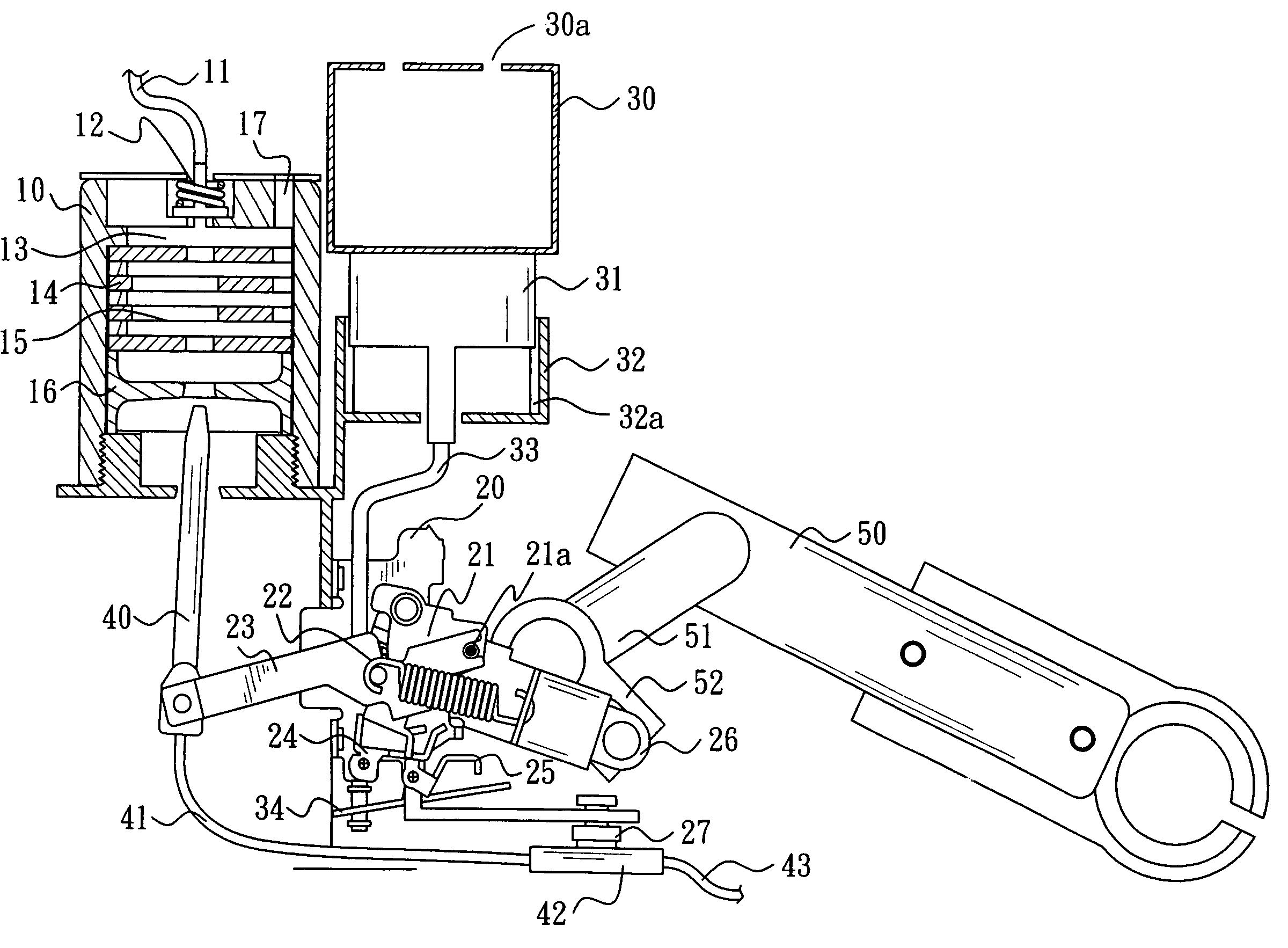
[0028]Please refer to FIG. 2 showing a perspective view of the present invention (accompanied by FIG. 3 showing a detailed illustration of the mechanism of the present invention). The present invention is related to an oil-immersed and high-pressure tripping switch structure, comprising an operational apparatus, an arc-extinguishing cylinder, and an oil-shortage automatic tripping safety device. The arc-extinguishing cylinder 10 includes an electrical side connecting wire 11, a fixed contact point 12, a spray-type arc-interrupting chamber 13, a side-blowing arc-quenching mechanism 14, a side-blowing arc-interrupting chamber 15, an aligning slide ring 16, and a sideway gas-ventilating channel 17. The operational apparatus is made up of a main support bracket 20, a rebound pivoting-point support 21, a spring rebound pivoting-point 21a, a main spring 22, a movable contact point crank 23, a tripper bracket 24, a trip trigger 25, a spring rotary arm 26, and an over-current magnetic tripp...


PUM


Abstract

An oil-immersed and high-pressure tripping switch structure comprises an operational apparatus, an arc-extinguishing cylinder, and an oil-shortage automatic tripping safety device wherein a sensory device detecting a fault current will trip open to displace a spring rebound pivoting-point, permitting a main spring to simultaneously actuate the release of contact points and the rotation of an operational handle therewith so that the operational handle is rotated to recover its primary angle so as to indicate the tripped/off status of the switch, facilitating the judgment and operation of workers. In addition, via a buoyant tube combined with an oil-retaining tank, the buoyant tube in case of oil-shortage can generate a sufficient downward pressure to activate the release of a tripping device so as to ensure the safety of the present invention in operation. Furthermore, a complex arc-interruption mechanism is applied so that the arc-extinguishing cylinder can efficiently break higher fault current thereby.

Description

BACKGROUND OF THE INVENTION[0001]The present invention is related to an oil-immersed and high-pressure tripping switch structure, comprising an operational apparatus, an arc-extinguishing cylinder, and an oil-shortage automatic tripping safety device wherein a sensory device detecting a fault current will trip open to displace a spring rebound pivoting-point, permitting a main spring to simultaneously actuate the release of contact points and the rotation of an operational handle therewith so that the operational handle is rotated to recover its primary angle so as to indicate the tripped / off status of the switch, facilitating the judgment and operation of workers. In addition, via a buoyant tube combined with an oil-retaining tank, the buoyant tube in case of oil-shortage can generate sufficient downward-pressure to activate the release of a tripping device so as to ensure the safety of the present invention in operation. Furthermore, a complex arc-quenching mechanism is applied so...

Claims


Application Information

Patent Timeline
Patent Type & Authority Patents(United States)
IPC IPC(8): H01H75/12
CPCH01H33/75H01H9/16
Inventor TSAI, YU TSAI
Owner JAKER ELECTRIC
Why Eureka
Try Eureka