Original feeding apparatus, original reading apparatus, and image forming apparatus

a feeding apparatus and reading technology, applied in the direction of electrographic process apparatus, thin material handling, instruments, etc., can solve the problems of inducing an increase in the size of the apparatus, and achieve the effect of reducing the leaning of the image reading portion, reducing the size of the apparatus, and ensuring stability

Inactive Publication Date: 2007-04-03
CANON KK
View PDF6 Cites 6 Cited by
  • Summary
  • Abstract
  • Description
  • Claims
  • Application Information

AI Technical Summary

Benefits of technology

[0020]In the above configuration, the variation is small in the position of the center of gravity of the image forming apparatus in the sliding operation of the image reading portion and the image forming apparatus can be stably installed. In addition, the image reading portion can be smoothly slid by a small slide force.
[0021]Since the above configuration suppresses the leaning of the image reading portion in the sliding operation in the shift direction, it is feasible to eliminate the cause of deformation on the apparatus frame, and this is also effective to stabilization of image quality.
[0022]Thanks to the above-stated configuration, the present invention decreases the variation in the position of the center of gravity of the image forming apparatus in the sliding operation of the image reading portion in the shift direction and permits the image forming apparatus to be stably installed. In addition, the image reading portion can be smoothly slid by a small slide force.
[0023]Since the above configuration suppresses the leaning of the image reading portion in the sliding operation in the shift direction, it is feasible to eliminate the cause of deformation on the apparatus frame, and this is also effective to stabilize image quality.
[0024]Since the reading position in the flow-reading mode is set on the rear end side with respect to the center in the shift direction, it is feasible to implement the reduction in size of the image reading portion.
[0025]Further, an original conveying motor is located on the rear end side in the shift direction and a sensor conveying motor of the original reading portion is located on the front end side in the shift direction, whereby a good balance is established between the centers of gravity of the original feeding apparatus and the image forming apparatus and the sliding range of the sensor conveying motor becomes small, thereby achieving a reduction in size of the apparatus.

Problems solved by technology

Further, if the sliding units themselves have an ill center of gravity balance, they will be slid while leaning to the center of gravity side, resulting in failure in smooth sliding.
Since the original edge butt member 55 in the book mode is located on the left side and the reading position in the flow-reading mode is further located on the left side, as shown in FIG. 7, the butt member 55 has to be positioned on the right side of the reading portion D. This necessitates increasing the lateral width of the original glass stand 54, which will lead to a problem of inducing an increase in size of the apparatus.

Method used


Image

  • Original feeding apparatus, original reading apparatus, and image forming apparatus
  • Original feeding apparatus, original reading apparatus, and image forming apparatus
  • Original feeding apparatus, original reading apparatus, and image forming apparatus

Examples


Embodiment Construction

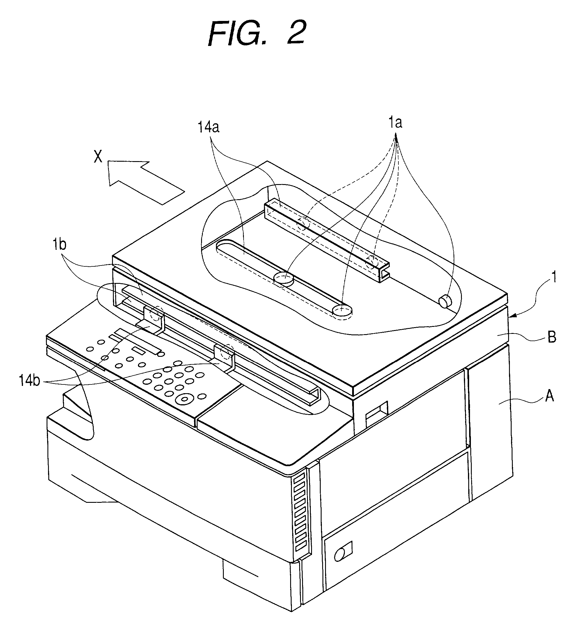
[0034]The image forming apparatus using the original feeding apparatus according to an embodiment of the present invention will be described below with reference to the drawings.

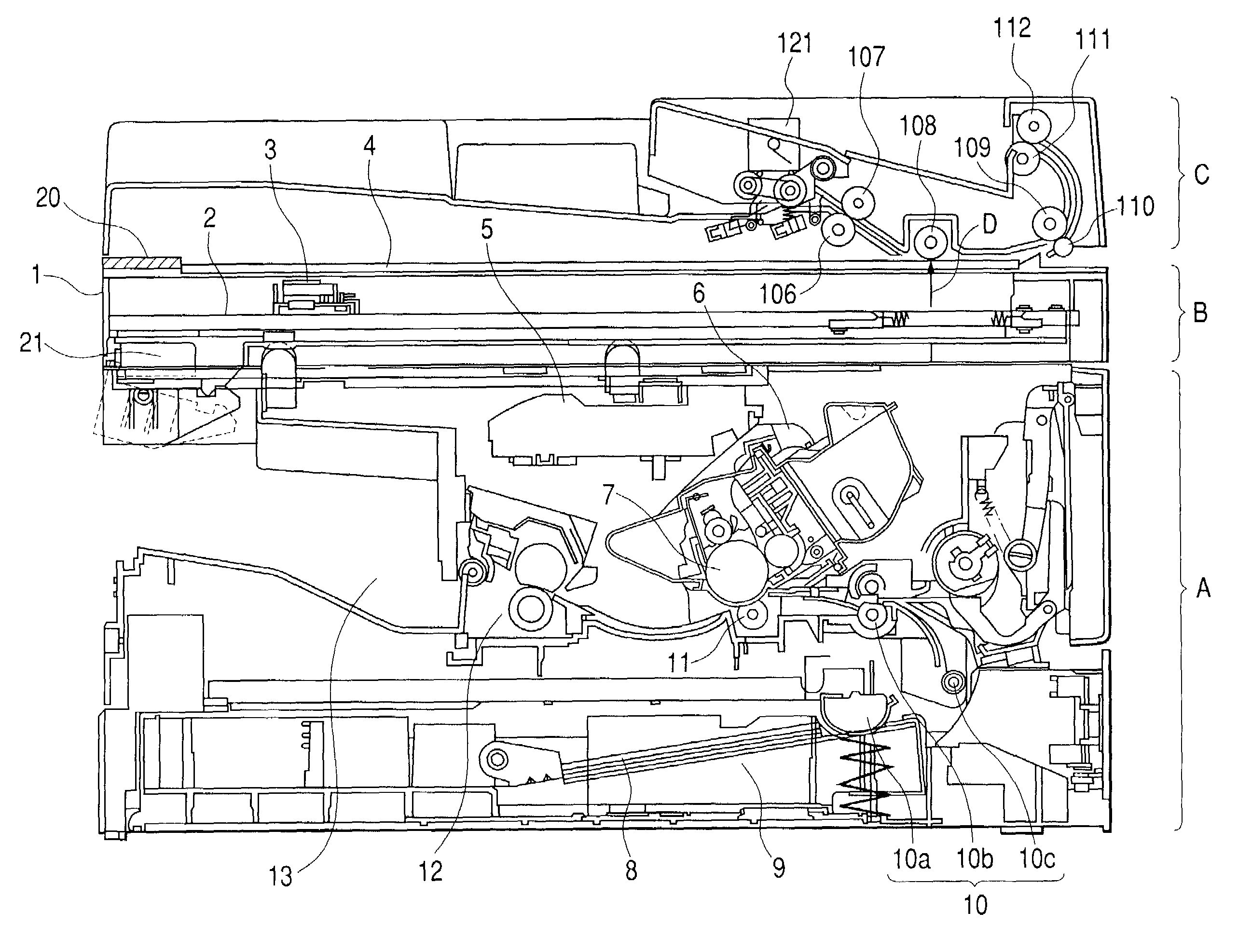
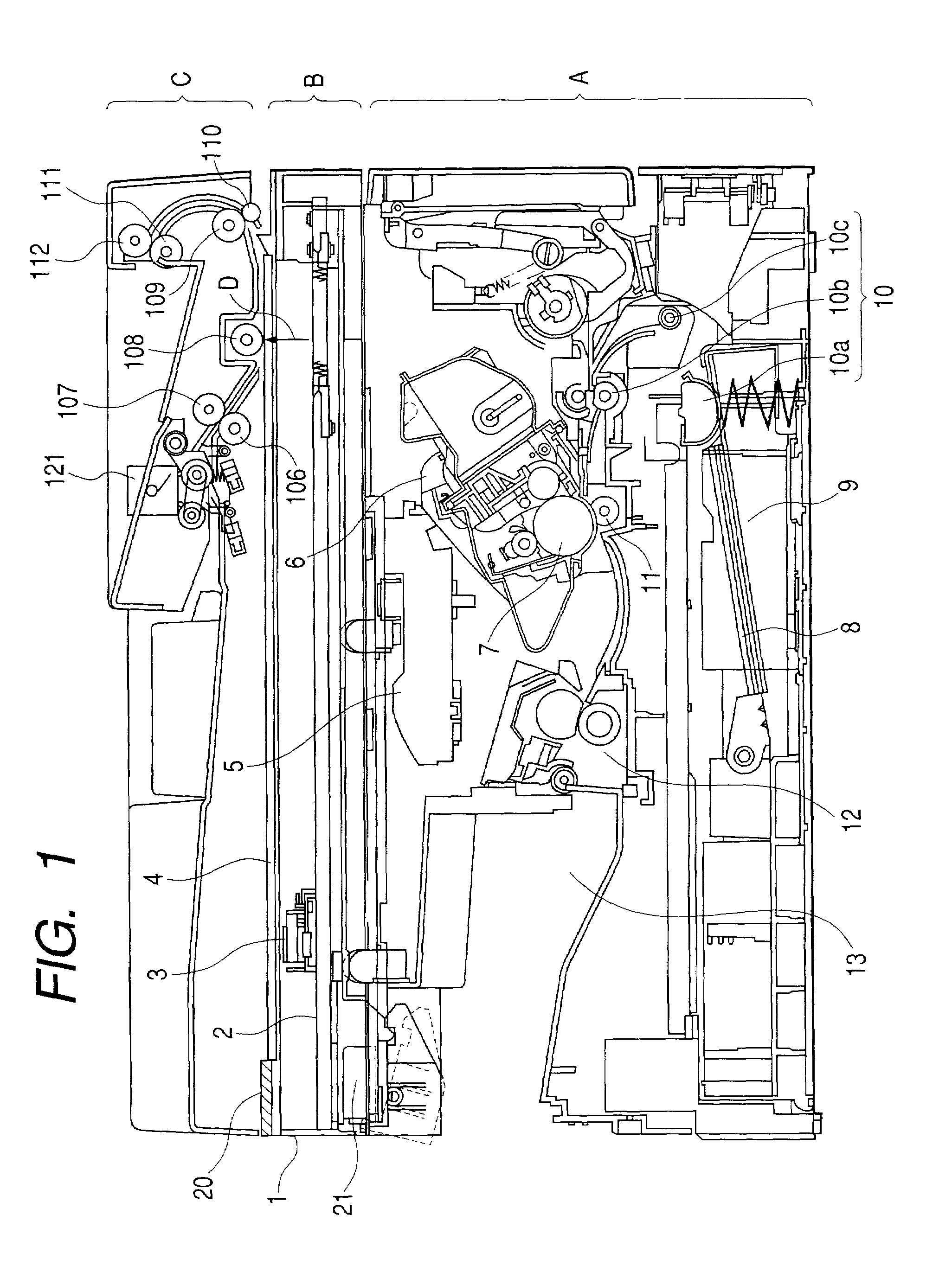
(Overall Configuration of Apparatus)

[0035]FIG. 1 is a front sectional illustration of the image forming apparatus of the present embodiment. The main body of the image forming apparatus (copying machine) shown in FIG. 1 is generally composed of an image forming portion A, an image reading portion B, and an original feeding apparatus C. The present embodiment will be described in a configuration wherein the image reading portion B and the original feeding apparatus C are independent of each other, but the present invention also presents like effect in a configuration wherein the image reading portion B and the original feeding apparatus C are integrated as an original reading apparatus.

[0036]The image reading portion B is constructed in the structure in which scanning rails 2 are located on the left and right...


PUM


Abstract

An original feeding apparatus is located above an image forming portion for recording an image on a recording medium and is constructed to convey an original to an image reading portion slidable in a slide direction relative to the image forming portion. The original feeding apparatus is slidable integrally with the image reading portion relative to the image forming portion and has its center of gravity located on the rear end side with respect to the center in the slide direction.

Description

BACKGROUND OF THE INVENTION[0001]1. Field of the Invention[0002]The present invention relates to an original feeding apparatus for feeding originals one by one from an original stack to a predetermined reading position in the main body of a copying machine, an original reading apparatus, and an image forming apparatus provided with them. More particularly, the invention relates to an original feeding apparatus installed in an image forming apparatus with a mechanism for sliding the original feeding apparatus and an image reading portion, and constructed to be able to decrease variation in the position of the center of gravity of the image forming apparatus in the sliding operation and reduce the apparatus in size, an original reading apparatus, and an image forming apparatus provided with them.[0003]2. Description of Related Art[0004]As conventional digital copying machines, facsimile machines, etc., there are image forming apparatuses consisting of an image forming portion A, an im...

Claims


Application Information

Patent Timeline
Patent Type & Authority Patents(United States)
IPC IPC(8): H04N1/04G03G15/00B65H5/06H04N1/00
CPCH04N1/00525H04N1/00533H04N1/00543G03G15/00
Inventor MANABE, KENICHIIWAMOTO, KAZUYUKI
Owner CANON KK
Why Eureka
Try Eureka