Dual connection power line parameter analysis method and system

a power line and parameter analysis technology, applied in the field of electric distribution, can solve the problems of arcing, arc fault, complex system that distributes electrical power for residential, commercial, industrial use,

Active Publication Date: 2007-04-03
ROCKWELL AUTOMATION TECH
View PDF21 Cites 37 Cited by
  • Summary
  • Abstract
  • Description
  • Claims
  • Application Information

AI Technical Summary

Problems solved by technology

Systems that distribute electrical power for residential, commercial, and industrial uses can be complex and widely divergent in design and operation.
A problem in the operation of MCCs and other power management systems, such as switchboards and panelboards, is the occurrence of arcing (also called an arc, arc fault, arcing fault, arc flash, arcing flash, etc.) which may be thought of as an electrical conduction or short circuit across the air between two conductors.
Initiation of an arc fault may be caused by a loose connection, build-up of foreign matter such as dust or dirt, insulation failure, or a short-circuit between the two conductors (e.g., a foreign object establishing an unwanted connection between phases or from a phase to ground) which causes the arc.
However, arcing faults can also comprise intermittent failures between phases or phase-to-ground.
In either case, the result is an intense thermal event (e.g., temperatures up to 35,000° F.) causing melting or vaporization of conductors, insulation, and neighboring materials.
Arcing faults can cause damage to equipment and facilities and drive up costs due to lost production.
These donning and doffing times can directly affect productivity.
Conventional methods for determining power line parameters and PPE levels rely on approximation techniques or require complex, extensive modeling of electrical equipment.

Method used


Image

  • Dual connection power line parameter analysis method and system
  • Dual connection power line parameter analysis method and system
  • Dual connection power line parameter analysis method and system

Examples


Embodiment Construction

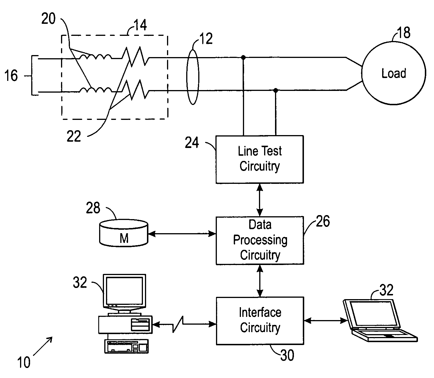
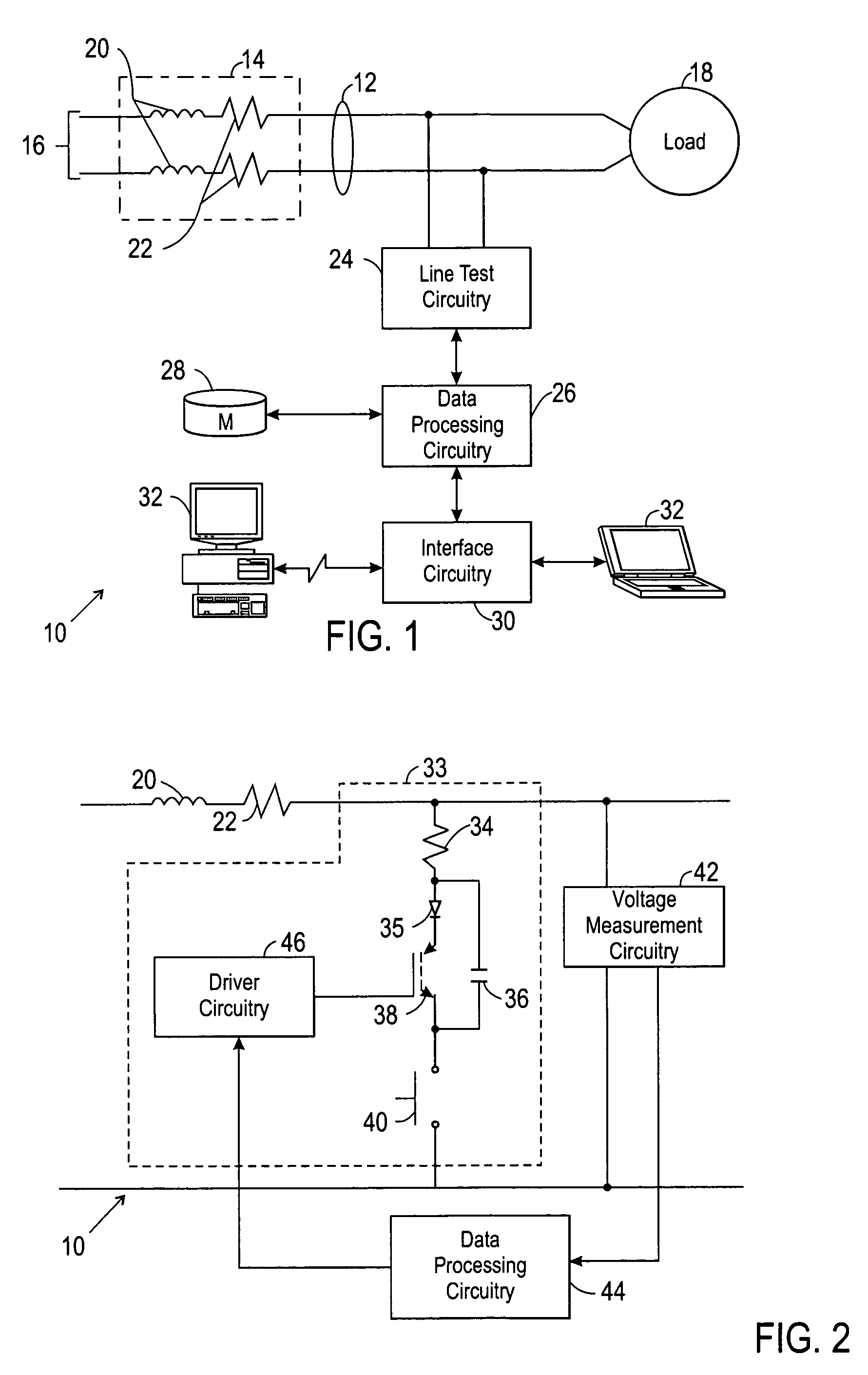
[0028]Turning now to the drawings, and referring first to FIG. 1, an impedance monitoring system is illustrated and designated generally by the reference numeral 10. The impedance monitoring system is illustrated in a single-phase application. That is, the system is illustrated for identifying the impedance of a single-phase power source. As will be appreciated by those skilled in the art, and as discussed in greater detail below, the system may be easily adapted for identifying impedance parameters of three-phase power lines and sources as well.

[0029]Impedance monitoring system 10 is illustrated as coupled to a pair of power supply lines 12. Power supply lines 12, and any upstream circuitry, such as transformers, connectors, and so forth are considered to have a net impedance illustrated by equivalent circuitry in box 14 of FIG. 1. The impedance 14 is, for the present purposes, considered to be a collective or cumulative impedance of the entire power supply network, represented gen...


PUM


Abstract

A method and apparatus is disclosed for determining the power line parameters of a system. Specifically, there is provided a method comprising perturbing a voltage waveform through a first connection, measuring a characteristic of the perturbation through a second connection, and calculating a line impedance based on the characteristic of the perturbation.

Description

BACKGROUND[0001]The present technique relates generally to the field of electrical distribution. Specifically, the invention relates to techniques for determining the impedance parameters of electrical power, for determining incident energy, for determining a flash protection boundary, and for determining a level of personal protective equipment (“PPE”) that may be required or advisable based upon the available energy and similar considerations.[0002]Systems that distribute electrical power for residential, commercial, and industrial uses can be complex and widely divergent in design and operation. Electrical power generated at a power plant may be processed and distributed via substations, transformers, power lines, and so forth, prior to receipt by the end user. The end user may receive the power over a wide range of voltages, depending on availability, intended use, and other factors. In large commercial and industrial operations, the power may be supplied as three phase ac power...

Claims


Application Information

Patent Timeline
Patent Type & Authority Patents(United States)
IPC IPC(8): G01R25/00
CPCG01R27/16
Inventor GASPERI, MICHAEL L.JENSEN, DAVID L.ROLLAY, DAVID T.
Owner ROCKWELL AUTOMATION TECH
Why Eureka
Try Eureka