Cruise missile recovery system

a recovery system and rocket technology, applied in the field of rocket recovery systems, can solve the problem that the parachutes cannot be guided to a location on earth

Inactive Publication Date: 2007-04-10
THE UNITED STATES OF AMERICA AS REPRESENTED BY THE SECRETARY OF THE NAVY
View PDF12 Cites 15 Cited by
  • Summary
  • Abstract
  • Description
  • Claims
  • Application Information

AI Technical Summary

Problems solved by technology

However, the parachutes cannot ...

Method used


Image

  • Cruise missile recovery system
  • Cruise missile recovery system
  • Cruise missile recovery system

Examples


Embodiment Construction

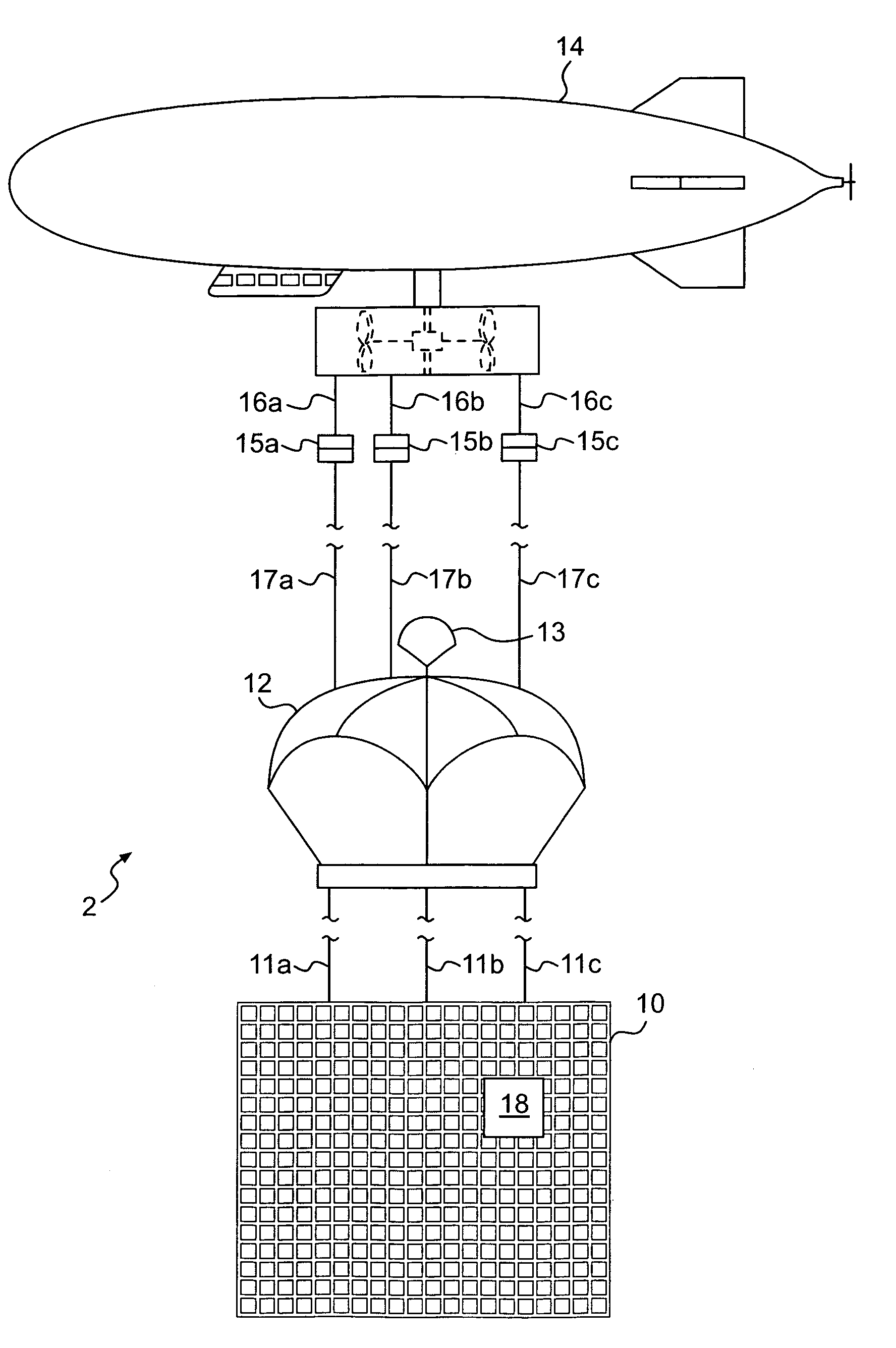
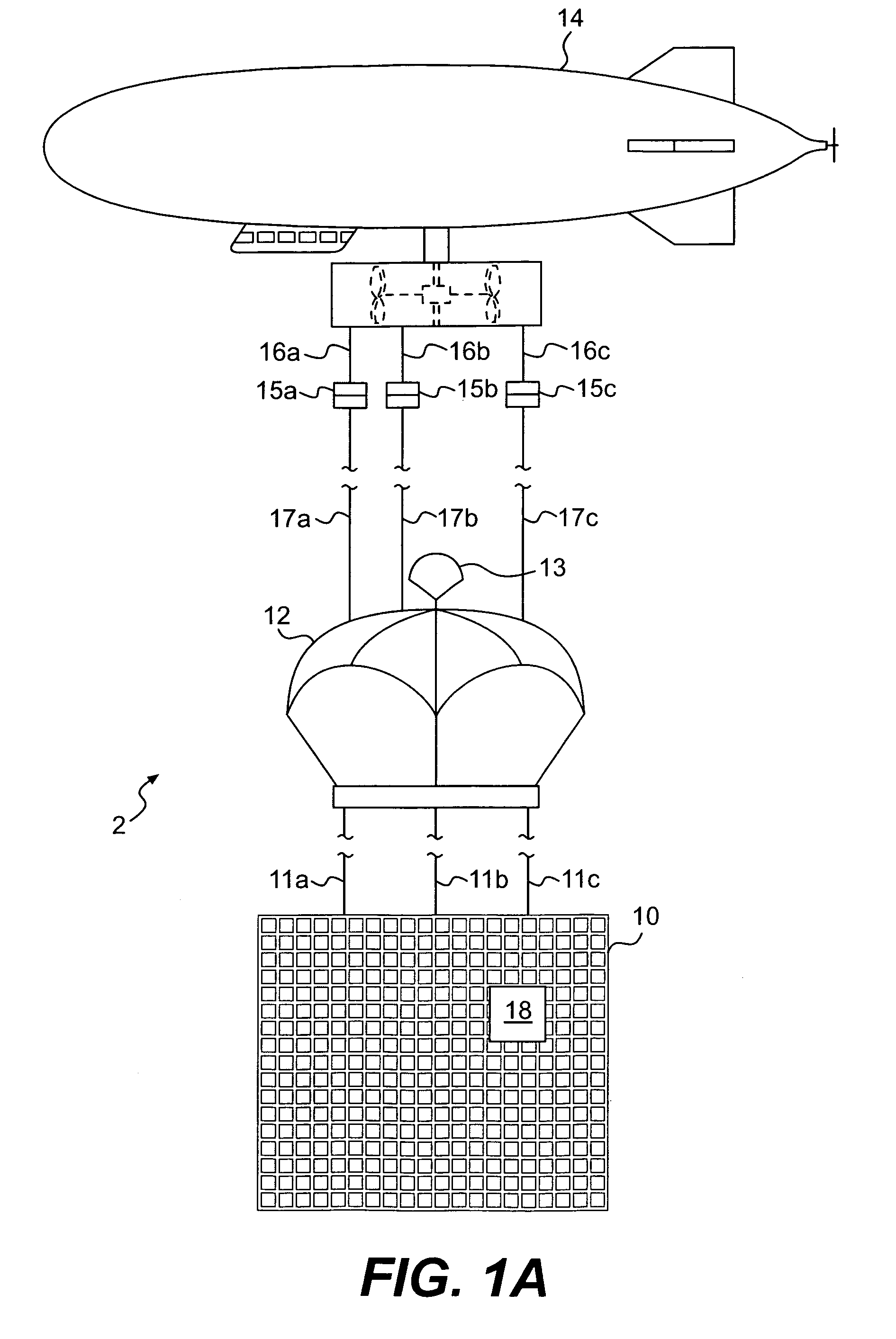
[0015]FIG. 1A is an embodiment of a cruise missile recovery system, cruise missile recovery system 2. The cruise missile recovery system 2 uses a net 10 to capture a test-type cruise missile. The net 10 is an intercept device. The net 10 is connected to cable 11a, 11b and 11c. The cables 11a, 11b and 11c, in turn, are connected to a radio-controlled parafoil 12. A drogue parachute 13 is also connected to the radio-controlled parafoil 12.

[0016]In FIG. 1A, a position-stabilized dirigible 14 suspends the parafoil 12 and the net 10 at a stable location above a point on the earth. The position-stabilized dirigible 14 is a position-stabilized suspension device. The position-stabilized dirigible 14 is connected to tension release couplings 15a, 15b and 15c. The tension release couplings 15a, 15b and 15c are connected to parafoil 12. The parafoil 12 is connected to the dirigible 14 by means of the tension release couplings 15a, 15b and 15c, cables 16a, 16b, 16c and cables 17a, 17b and 17c. ...


PUM


Abstract

A cruise missile recovery system, for capturing a flying cruise missile and for guiding the cruise missile to a landing spot. The cruise missile recovery system has an intercept device for capturing the flying cruise missile, a radio-controlled parafoil connected to the intercept device for allowing the intercept device and cruise missile to be guided to the landing spot during descent of the intercept device and cruise missile, after capture of the flying cruise missile by the intercept device, and a position-stabilized suspension vehicle for suspending the radio-controlled parafoil device and the intercept device at a stable location above the earth, prior to capture of the flying cruise missile by the intercept device.

Description

BACKGROUND OF THE INVENTION[0001]In U.S. Pat. No. 5,583,511, an intercept device is used for snagging a flying vehicle. The purpose of the intercept device is to hinder further flight of the flying vehicle, such as a jet aircraft.[0002]The '511 patent shows that the intercept device can be connected to drag producing devices, such as parachutes. The parachutes decrease speed of descent of the intercepted vehicle. However, the parachutes cannot be guided to a location on the earth.[0003]In the '511 patent, the intercept device is deployed from a missile. The missile is flown in front of the flying vehicle. The intercept device is then deployed by means of the missile. The flight path of the missile intersecting the flight path of the flying vehicle. The intercept device intersects the flight path of the flying vehicle.[0004]The present invention is a cruise missile recovery system for capturing a flying cruise missile, and for guiding the cruise missile to a landing spot. The recover...

Claims


Application Information

Patent Timeline
IPC IPC(8): B64D5/00B64C31/00B64D17/80
CPCF41H11/02F41H11/04
Inventor FLAMMER, MARK S.
Owner THE UNITED STATES OF AMERICA AS REPRESENTED BY THE SECRETARY OF THE NAVY
Why Eureka
Try Eureka