
New casting method and casting die

A technology for casting molds and castings, which is applied in the field of casting molds implementing the method, and can solve problems such as troublesome operation, low yield, and high cost of castings

Inactive Publication Date: 2009-05-06
曾奇中
View PDF0 Cites 6 Cited by
  • Summary
  • Abstract
  • Description
  • Claims
  • Application Information

AI Technical Summary

Problems solved by technology

[0012] 3. The effect of unidirectional pressure feeding is poor, and it is impossible to realize multi-directional, multi-position pressure feeding and local pressure feeding, which makes it difficult to cast large-scale castings with large wall thickness and complex structure;
[0013] 4. The cooling method is restricted, the cooling speed is slow, and the mechanical properties and mechanical properties of castings need to be improved;
[0014] 5. The yield rate of automobile and motorcycle castings such as wheels is low (for example, the casting of many wheels has returned to gravity casting);
[0015] 6. The pouring conditions are relatively unstable during mass production, which affects the stability of product quality and yield, and the productivity is not high;
[0016] 7. It needs a complete set of equipment such as liquid riser, pressure source and liquid level control system, low-pressure casting machine and a wide site, and the casting cost is high;
[0017] 8. It is required to strictly grasp the pressurization specification, control the temperature field of sequential solidification, have high requirements on the quality of the operators, have many technical difficulties, high scrap rate, and troublesome operation

Method used


Image

  • New casting method and casting die
  • New casting method and casting die
  • New casting method and casting die

Examples


Embodiment Construction

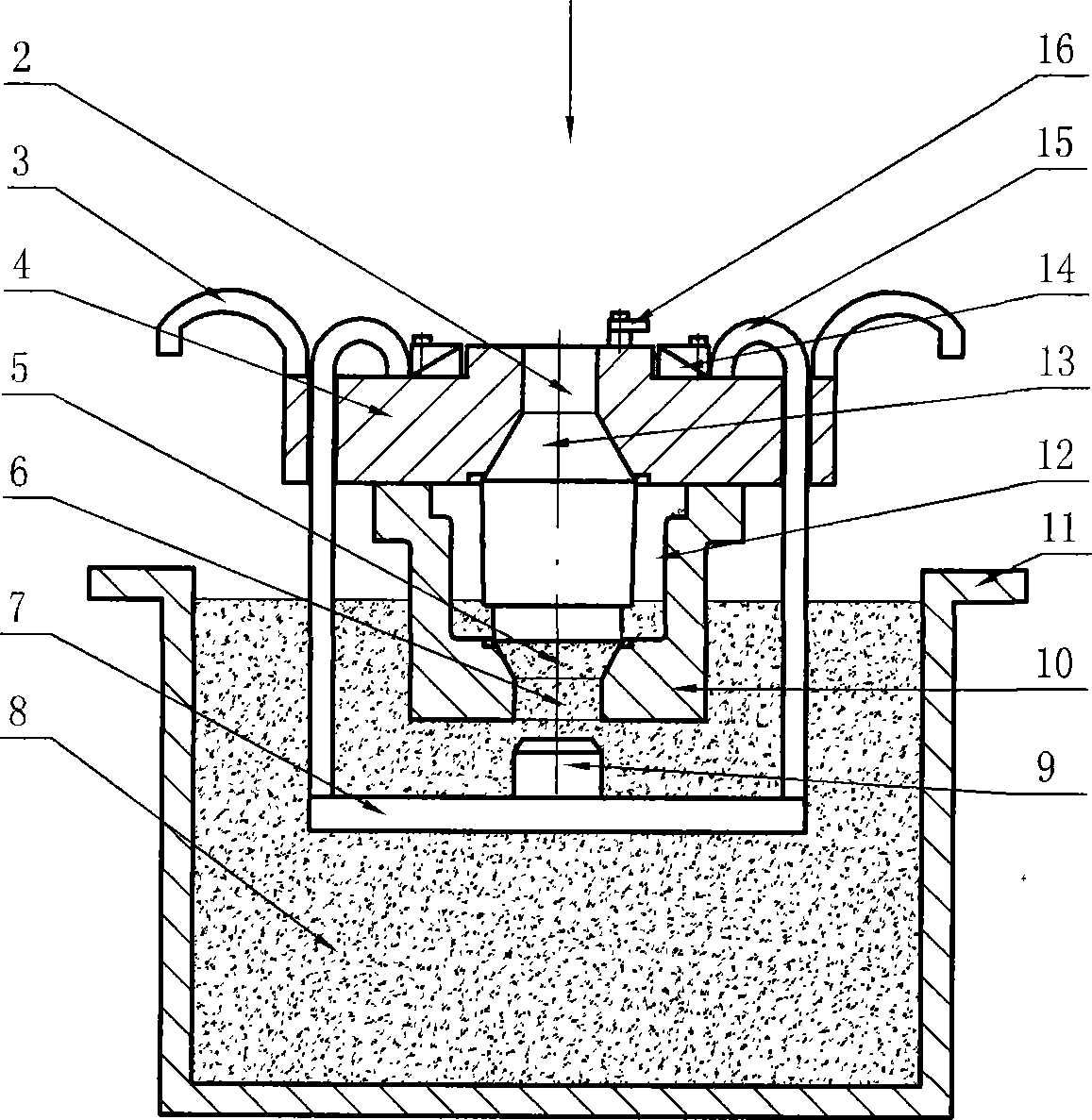
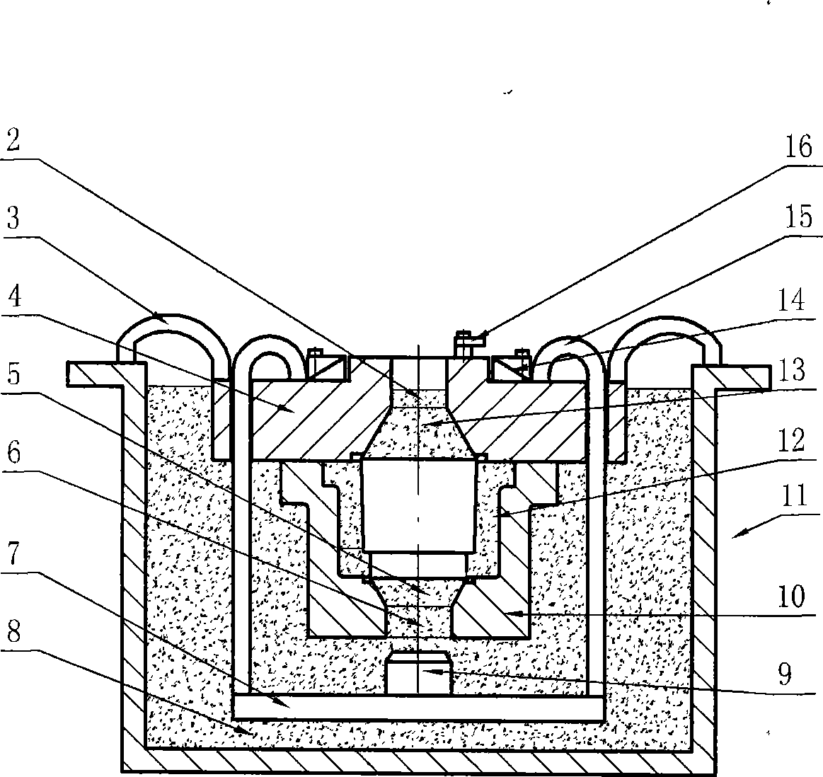
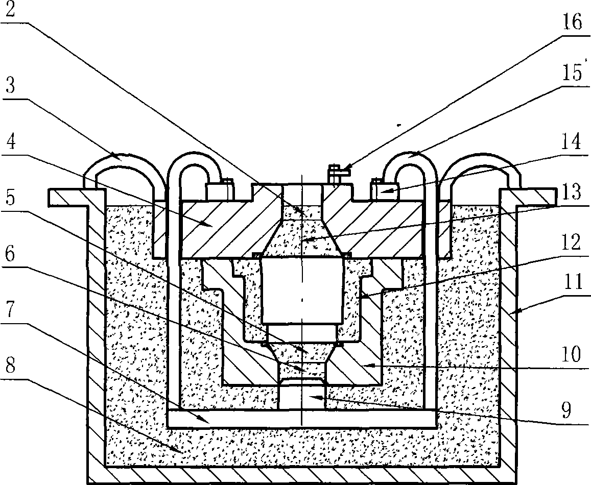
[0069] The casting mold has a simple structure, and the specific structure has been introduced before, and the specific implementation will be described in conjunction with the operation process below.

[0070] The operating process of the present invention comprises the following steps:

[0071] 1. Preparation,

[0072] a. Smelting molten metal. For large casting molds, the molten metal should be placed in a molten pool of a corresponding size and kept warm. (Taking aluminum alloy as an example) the heat preservation temperature can be 10-30°C lower than that of conventional low-pressure casting. The molten metal is generally controlled Between 690~715℃,

[0073] b. Preheat the casting mold and paint under the same conditions as conventional low-pressure casting,

[0074] c. Complete the assembly of the casting mold and paint the outside of the casting mold;

[0075] 2. Use a sling or a hook on the crane to hook the fixed ring 3 on the casting mold, slowly immerse the cast...


PUM

PropertyMeasurementUnit
diameteraaaaaaaaaa

Abstract

The invention discloses a new casting method, wherein, a casting mold with a pressurizing device is immerged in the inside of molten metal (8) for casting; the pressuring device is driven to carry out pressurization by utilizing lifting force and the gravity of the casting mold or other power. The molten metal in a die cavity (12) is filled, fed and solidified under necessary pressure during the lifting process, and then the casting mold is immerged in water for chilling so as to improve the mechanical property of castings. An upper mold (4) and a lower mold (10) of the casting mold are respectively provided with a plunger hole which is communicated with the die cavity (12) by a feeding cavity; the feeding cavity is slantingly arranged at the thickness changing site of the castings, and a driving mechanism is connected on the plunger to be matched with the plunger hole. The molten metal in the die cavity (12) is pressurized under the action of the driving mechanism, thus causing the castings to be filled, fed and solidified under single directional, double directional and multi directional high-pressure pressurizing. The method is suitable for the casting of various complicated aluminum alloy castings such as the cylinder of an auto engine, wheel hub and extra large thin wall aluminum alloy castings such as cruise missile hull with 0.8m in diameter, 6m in length and 6-8mm in thickness and various common castings.

Description

technical field [0001] The invention relates to a casting method and a casting mold, specifically, a casting mold with a pressurizing device is immersed in molten metal for pouring, and the lifting force and the gravity of the casting mold are used as power or other power to drive the pressurizing device to pressurize. A casting method is provided, and a casting mold for implementing the method is provided. Background technique [0002] The current casting methods generally include gravity casting, vibration casting, centrifugal casting, pressure casting, low pressure casting, differential pressure casting, vacuum suction casting, liquid extrusion, semi-solid casting, metal casting, sand casting, investment casting, ceramic casting There are several methods such as casting, plaster casting, lost foam casting, continuous casting, semi-continuous casting, squeeze casting, etc. Among them, gravity casting and vibration casting have poor filling and shrinkage, which are prone to...

Claims


Application Information

Patent Timeline
Patent Type & Authority Applications(China)
IPC IPC(8): B22D23/04
Inventor 曾奇中
Owner 曾奇中
Learn More