Vehicle bumper

a technology for vehicles and bumpers, applied in the direction of bumpers, vehicle components, pedestrian/occupant safety arrangements, etc., can solve the problems of low energy-absorption performance of energy-absorbing components, adversely affecting the appearance of vehicles and engine cooling performance, etc., and achieve favorable load characteristics and favorable load characteristics

Inactive Publication Date: 2007-04-10
HONDA MOTOR CO LTD
View PDF14 Cites 21 Cited by
  • Summary
  • Abstract
  • Description
  • Claims
  • Application Information

AI Technical Summary

Benefits of technology

[0012]The provision of the head extended from the front upper surface or the front lower surface of the body upward or downward can provide a load allowable for the protection of a leg in the initial stages of a collision.
[0014]In addition, the provision of the space rearward of the head allows a sufficient impact-absorbing stroke of the bumper, providing favorable load characteristics.
[0015]Accordingly, throughout the head of the bumper, a load allowable for the protection of a leg in the initial stages of a collision can be obtained, and also favorable load characteristics can be obtained.
[0016]Preferably, the bumper beam is an aluminum extrusion, and is provided with mating holes in a midsection thereof in a transverse direction; and the energy-absorbing member is provided with protrusions to be fitted into the mating holes, and is provided at laterally opposite ends thereof upper and lower hooks to engage upper and lower flanges provided at the top and bottom of the front surface of the bumper beam. Thus, the protrusions of the energy-absorbing member can be fitted into the mating holes of the bumper beam, and the upper and lower hooks of the energy-absorbing member can be engaged with the upper and lower flanges of the bumper beam. Accordingly, the energy-absorbing member can be easily mounted to the bumper beam.

Problems solved by technology

The energy-absorbing member 104, however, has low energy-absorption performance because it consists of the support walls 103 and has a limited vertical length.
This will cause a new problem of adversely affecting the appearance of the vehicle and the engine cooling performance.

Method used


Image

  • Vehicle bumper
  • Vehicle bumper
  • Vehicle bumper

Examples


Embodiment Construction

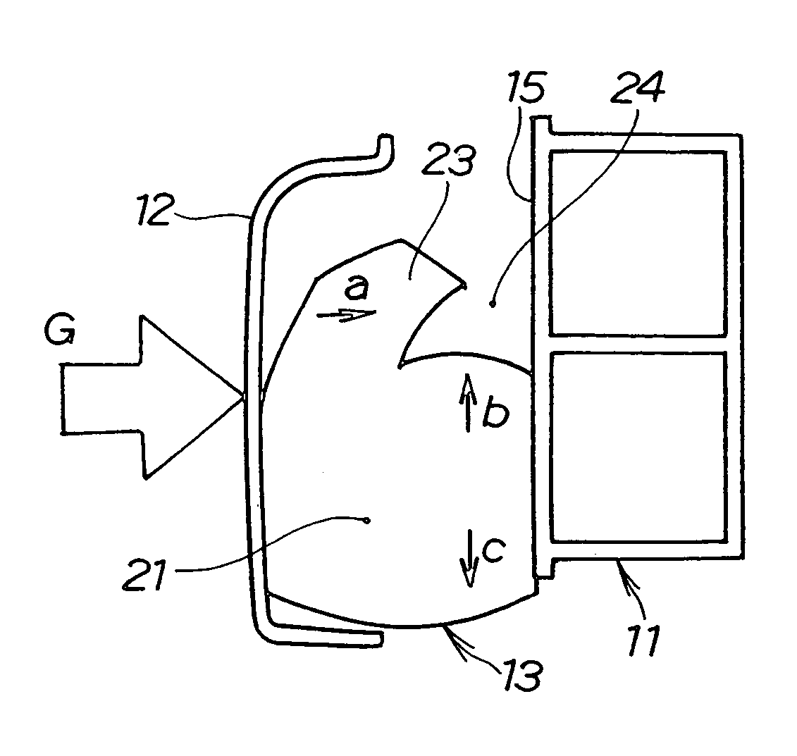
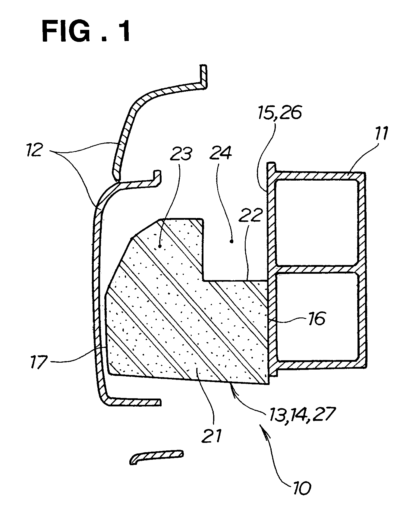
[0030]A vehicle bumper 10 according to the present invention shown in FIG. 1 includes a bumper beam 11, a bumper face 12 constituting the front end of a vehicle, and an energy-absorbing member 13 interposed therebetween. The energy-absorbing member 13 is made from a foam material 14.

[0031]A front surface 15 of the bumper beam 11 abuts a rear surface 16 of the energy-absorbing member 13. A front surface 17 of the energy-absorbing member 13 is opposite to the bumper face 12.

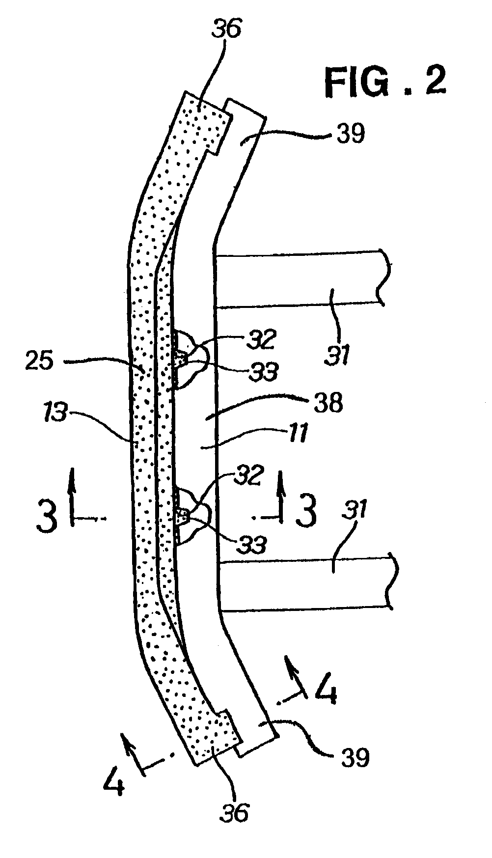
[0032]The energy-absorbing member 13 includes a body 21 and a head 23 extending upward from an upper surface 22 of the body 21, and is an L-shaped cross-section member formed to provide a space 24 between the head 23 and the front surface 15 of the bumper beam 11. The energy-absorbing member 13 further includes a straight central portion 25 and rearwardly retreating end portions 36 disposed at each end of the straight central portion 25.

[0033]More specifically, the vehicle bumper 10 in the present invention include...


PUM


Abstract

A vehicle bumper includes a bumper beam, a bumper face and an energy-absorbing member provided between the bumper beam and the bumper face. The energy-absorbing member has an L-shaped cross-section and includes a head of a front upper portion protruding upward. A space is formed between the bumper beam and the head. When a collision load acts on the bumper face, the head is deformed toward the space, thus absorbing the impact energy.

Description

FIELD OF THE INVENTION[0001]The present invention relates to vehicle bumpers for reducing the degree of injury to a pedestrian's leg.BACKGROUND OF THE INVENTION[0002]Vehicle bumpers in the related art including a bumper beam, a bumper face covering the front surface of the bumper beam, and an energy-absorbing member interposed therebetween, for reducing the degree of injury to a pedestrian's leg are proposed in Japanese Patent Laid-Open Publication Nos. 2004-155313 and HEI-11-208389, for example. The vehicle bumper in 2004-155313 will be described with reference to FIGS. 11A and 11B; the vehicle bumper in HEI-11-208389 will be described with reference to FIGS. 12A and 12B.[0003]FIG. 11A shows a bumper structure 100 with an energy-absorbing member 104 including a plurality of support walls 103 interposed between a bumper beam 101 and a bumper face 102, in a state of collision with a pedestrian's leg 105.[0004]When the bumper face 102 strikes a portion 106 below the knee, a thigh 107 ...

Claims


Application Information

Patent Timeline
Patent Type & Authority Patents(United States)
IPC IPC(8): B60R19/22
CPCB60R19/18B60R21/34B60R2019/182B60R2019/1873
Inventor KASHIWAGI, MASAKAZUMINAMI, HIDEKI
Owner HONDA MOTOR CO LTD
Why Eureka
Try Eureka