Coin dispensing device

a coin and dispensing technology, applied in coin dispensers, instruments, indoor games, etc., can solve the problems of user disturbance, clink noise, and inability to quickly hold the ball, so as to prevent the return of the first coin and prevent the result of the clink noise

Active Publication Date: 2007-04-10
ASAHI SEIKO CO LTD
View PDF10 Cites 4 Cited by
  • Summary
  • Abstract
  • Description
  • Claims
  • Application Information

AI Technical Summary

Benefits of technology

[0016]One aspect of this present invention is to prevent the returning of the first coin, and prevent the result of the clink noise.
[0017]To solve this problem, this present invention provides a coin dispensing device in which coins are dispensed to a guiding unit by a rotating disk one by one. The dispensed coins are guided upwards by said guiding unit in a line. The device includes a preventing unit to prevent the first coin going backward. The preventing unit is located adjacent to a rotating disk. The first coin which was dispensed by said rotating disk is prevented from moving backwards.
[0019]The preventing unit that prevents the first coin from going backwards may be a roller. With this structure, when the coins move to reverse, the first coin is stopped by the preventing unit which has contact with the first coin, because the roller cannot rotate. On the one hand, when the first coin passes the peripheral surface of the roller, the first coin can pass by applying a small force. Accordingly, the resistance of the rotating disk is slightly increased. Therefore the reverse movement of the first coin is prevented from the “clink” effect.
[0021]The roller may be guided by a guiding section in, wherein the roller approaches to a guiding surface and the rotating disk. In this structure, the roller is guided by the slanting elongate hole, wherein the roller approaches the guiding surface and the rotating disk. In other words, when the coin moves to the reverse direction, the roller moves near to the rotating disk, because the roller is drawn by the coin. The roller which is guided by the slanting elongate hole moves near the guiding surface. Accordingly, the pushing force which pushes the coin to the guiding surface increases. Therefore the holding force between the roller and the guiding surface increases, and the coin is held. The reverse movement of the coin is prevented, and the clink is prevented.

Problems solved by technology

Therefore it makes a “clink” noise.
In an operating machine where this device is situated, a user may be disturbed by the noise.
If the coin passageway slants, the ball cannot be held quickly.
Therefore, the time to hold of the coin takes longer.

Method used


Image

  • Coin dispensing device
  • Coin dispensing device
  • Coin dispensing device

Examples


Embodiment Construction

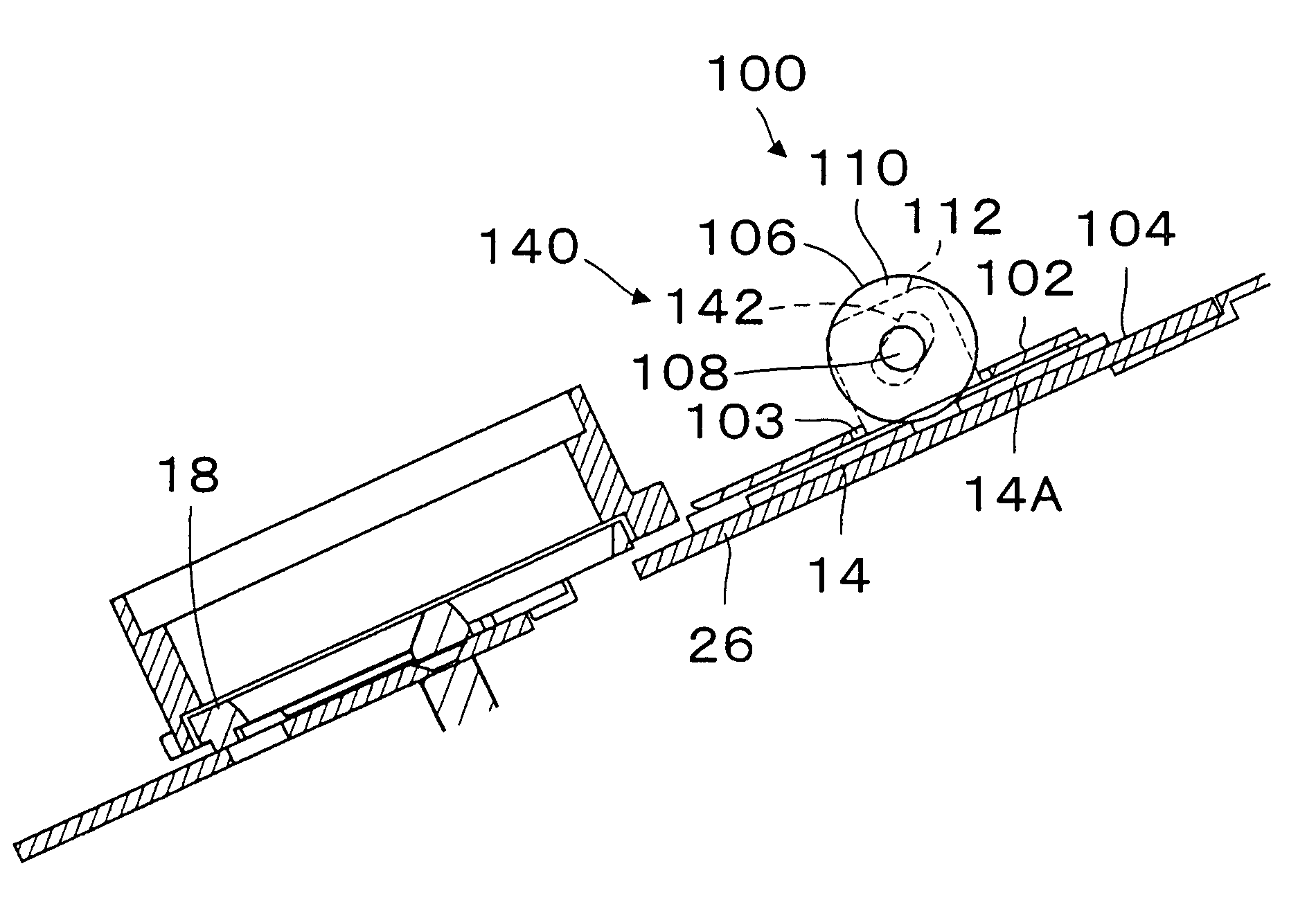
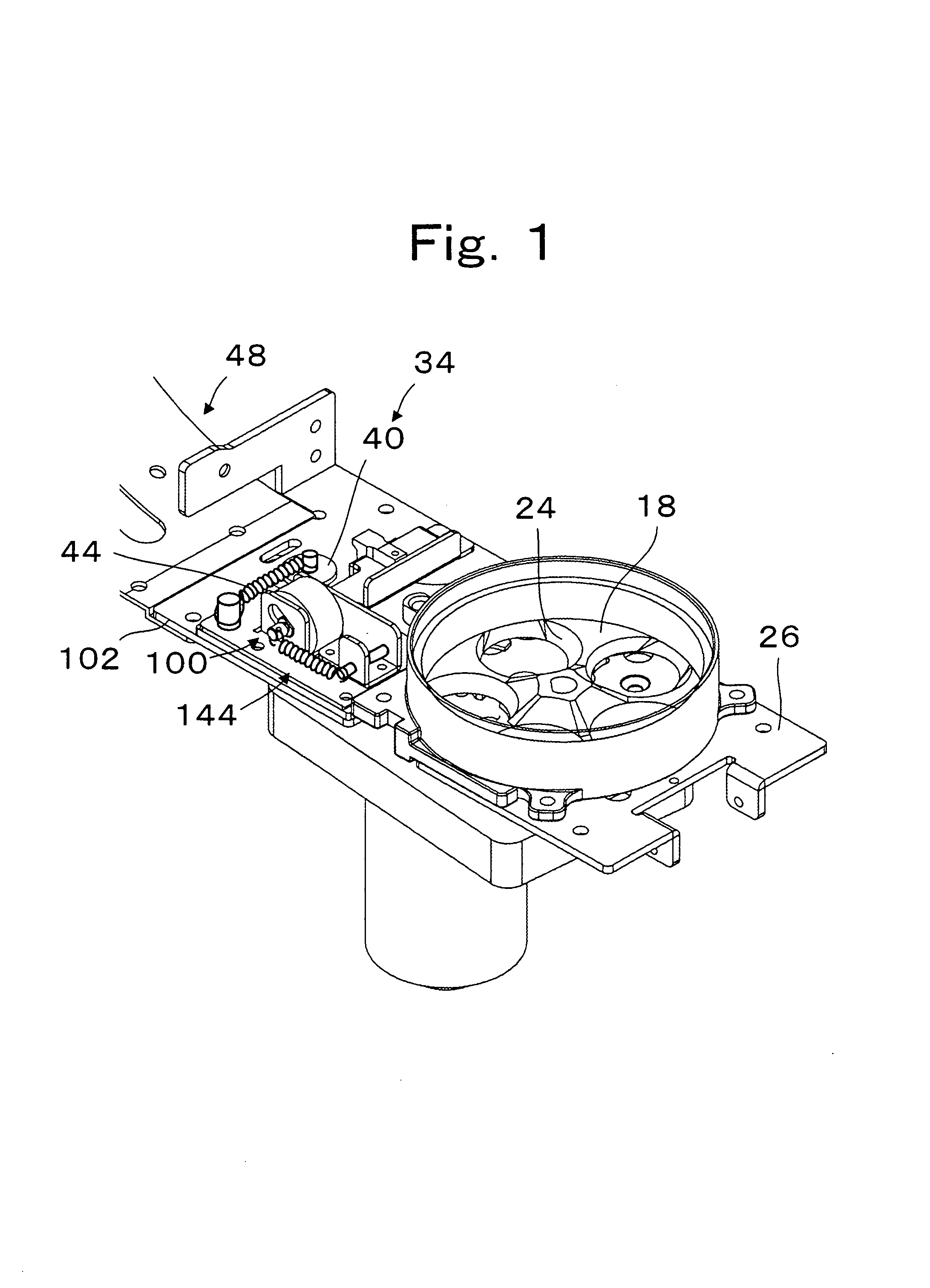
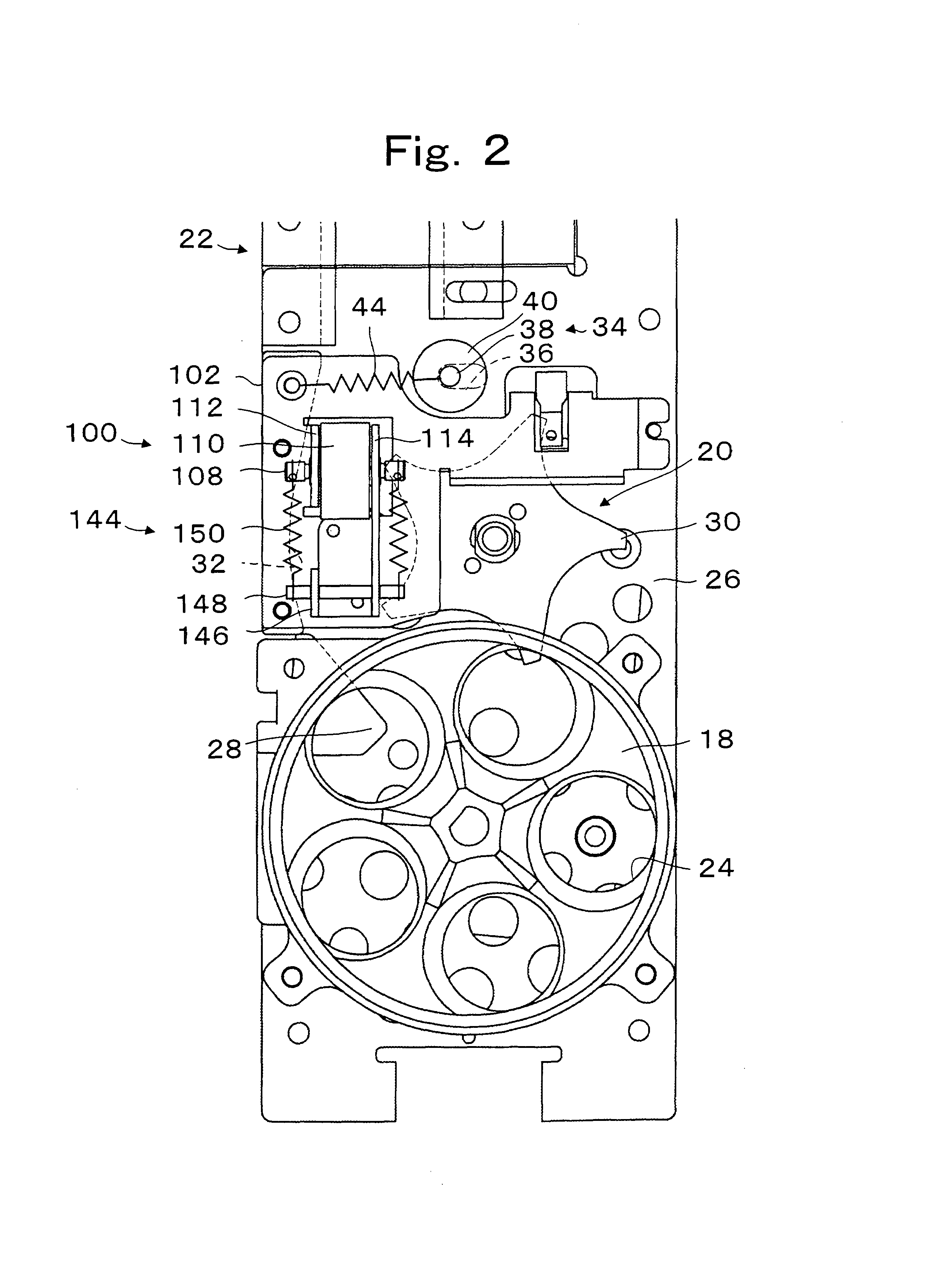
[0035]Referring to the drawings and in particular to FIGS. 1 to 5, the parts are designated by numbers that are the same as in FIGS. 6 and 7, and the different and additional structures are explained using additional reference numbers. In FIG. 1, a preventing unit 100 is provided to return a first coin. The preventing unit 100 is fixed on a guiding plate 102 which defines the upper section of a coin passageway 46. The preventing unit 100 has a function in which when a first coin 14 is dispensed from the second rotating disk 20, the coin cannot return to the side of the second rotating disk 20.

[0036]The preventing unit 100 includes a roller 110 which can rotate on shaft 108. The roller 110 is located near a guide surface 104 of a base 26. The distance between a peripheral surface 106 of the roller 110 and the guiding surface 104 is smaller than the thickness of coin 14 or is zero. In other words, the peripheral surface 106 and guiding surface 104 are in contact. The lower section of ...


PUM


Abstract

A coin dispensing device is provided that prevents a returning of a first coin to prevent a clink noise. The coin dispensing device has a rotating disk that dispenses coins to a guiding unit one by one. The dispensed coins are guided upwards by the guiding unit in a line. A coin return preventing unit prevents the first coin going backward which is located adjacent to the rotating disk. The first coin dispensed by the rotating disk is prevented from moving backwards.

Description

CROSS REFERENCE TO RELATED APPLICATIONS[0001]This application claims the benefit of priority under 35 U.S.C. § 119 of Japan Application No. 2003-381829 filed Nov. 11, 2003, the entire contents of which are incorporated herein by reference.FIELD OF THE INVENTION[0002]This present invention is related to a coin dispensing device in which a reverse movement of aligned coins is prevented. More particularly, the present invention is related to a backwards motion prevention unit for preventing coins which have been dispensed by the rotating disk and fall down, from running into the rotating disk and making noise such as a clunk. Furthermore, the present invention relates to a coin dispensing device where the returning movement of the dispensed coins which are dispensed by the rotating disk is held at a position so as not to make noise. In this specification, “coin” includes coins, tokens, discs, etc.BACKGROUND OF THE INVENTION[0003]A first prior art reference (Japanese Patent number 25148...

Claims


Application Information

Patent Timeline
Patent Type & Authority Patents(United States)
IPC IPC(8): G07D1/00A63F5/04B65G29/02G07D3/06G07D9/00
CPCG07D3/06
Inventor ABE, HIROSHI
Owner ASAHI SEIKO CO LTD
Why Eureka
Try Eureka