

Mobile telephone terminal apparatus having television telephone function
- Summary
- Abstract
- Description
- Claims
- Application Information
AI Technical Summary
Benefits of technology
Problems solved by technology
Method used
Image

Examples
first embodiment
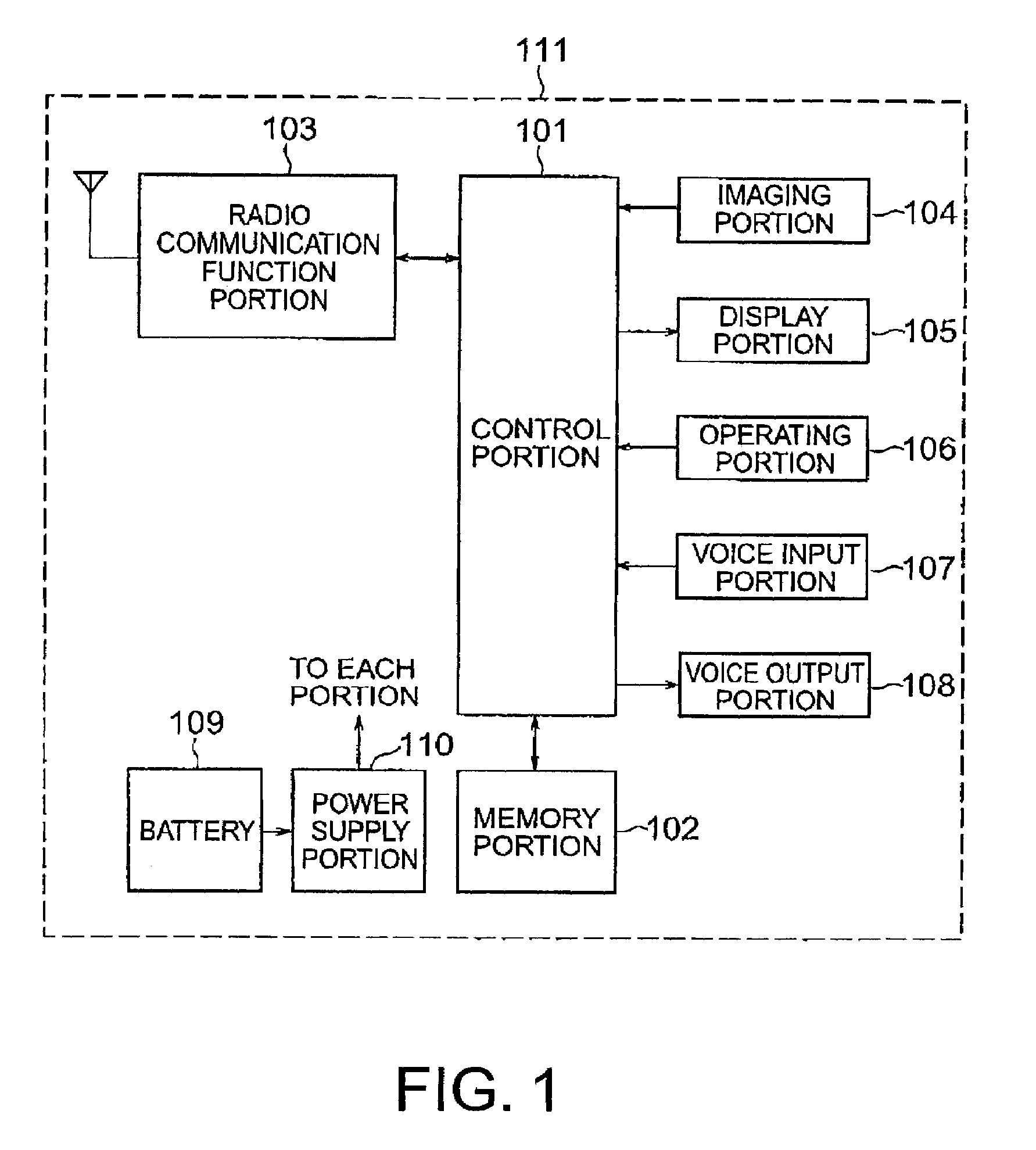
[0039]As shown in FIG. 1, the mobile telephone terminal apparatus includes a control portion 101, a memory portion 102, a radio communication function portion 103, an imaging portion 104, a display portion 105, an operating portion 106, a voice input portion 107, a voice output portion 108, a battery 109, and a power supply portion 110.
[0040]The control portion 101 totally controls components of the mobile telephone terminal apparatus body 111 under control of a program such that communication with image transmission can be implemented. The memory portion 102 stores a program for the control portion 101, image data, a table for setting a number of pixels to be sent, which will be described later, a table for setting a number of image frames to be sent and so on. The memory portion 102 exchanges data with the control portion 101. The radio communication function portion 103 includes an antenna and exchanges radio waves in a predetermined frequency band with a base station (not shown...
second embodiment
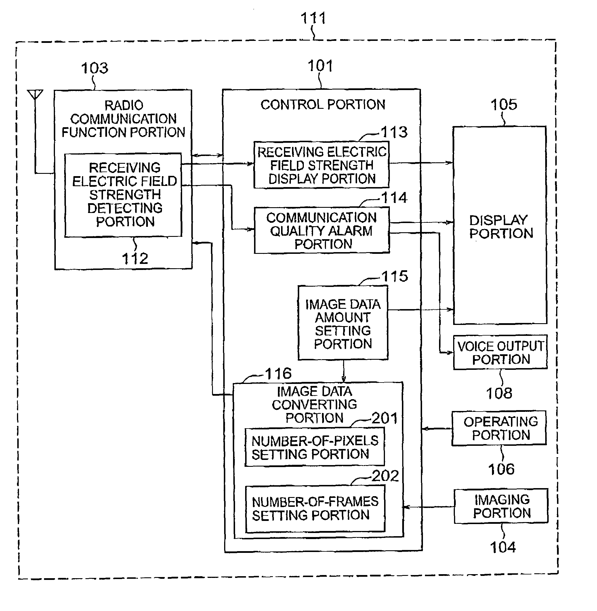
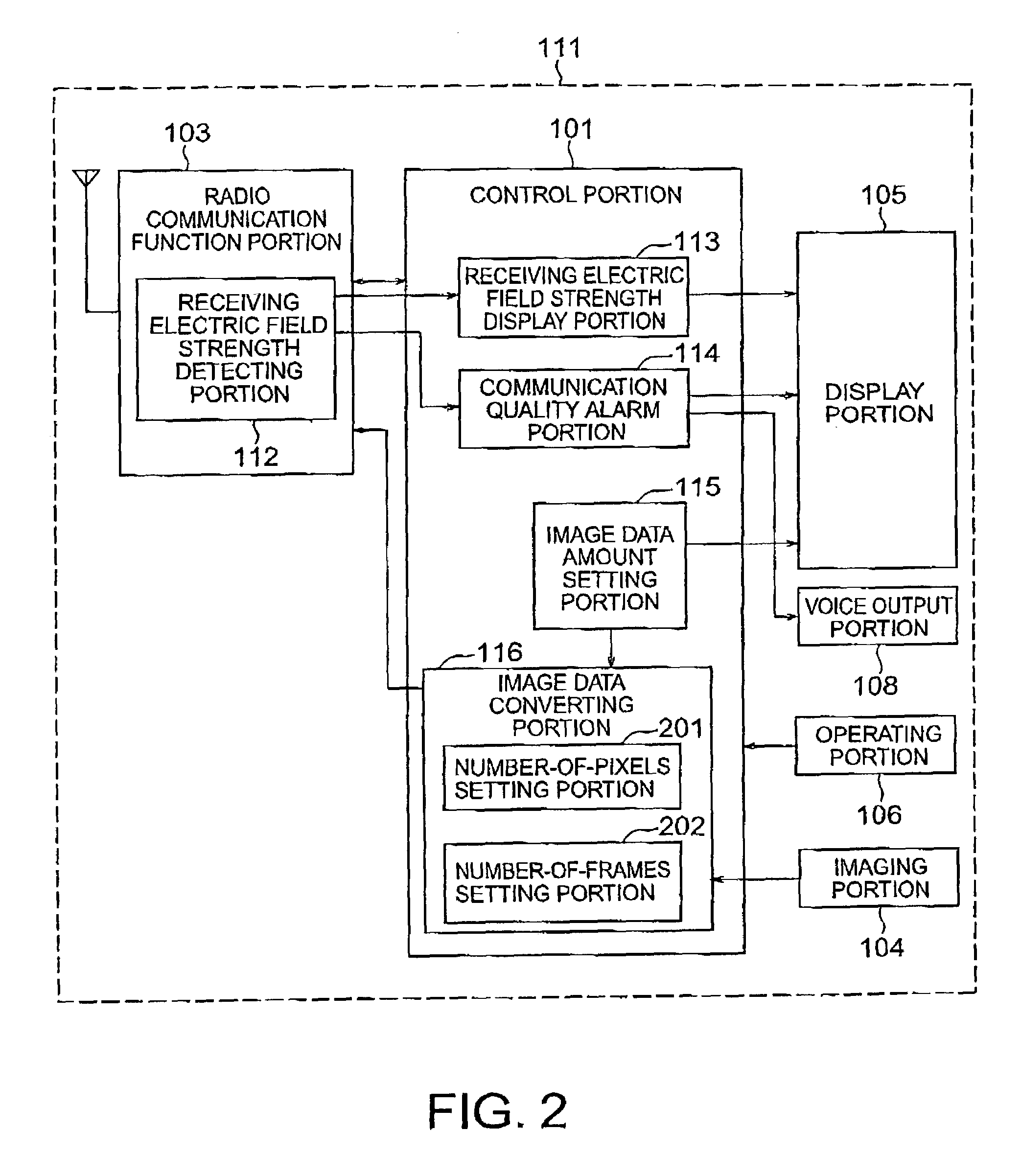
[0090]The second embodiment is the case where numbers of pixels and frames of an image are set in advance in the image data converting portion 116 when a weak battery alarm occurs. However, these numbers may be set arbitrarily. Thus, a data amount of an image to be sent may be set in accordance with a request from a user. As a result, communication with image transmission is possible with desired minimum quality.
[0091]The second embodiment is the case where a single number of pixels and a single number of frames are set for an image by the image data amount setting portion 115. However, the numbers may be set in multiple levels in accordance with a given battery remaining amount. Thus, a data amount of an image to be transmitted can be suppressed in accordance with a given battery remaining amount.
[0092]According to the second embodiment, both of the number-of-frame setting portion 202 and the number-of-pixels setting portion 201 are provided, and both of the numbers of frames and p...
third embodiment
[0100]The third embodiment describes the case where the external imaging portion 801 and the mobile telephone terminal apparatus body 111 are connected through the external connection terminal. However, a transmission portion (not shown) may be provided in the mobile telephone terminal apparatus body 111, and transmission may be performed through the transmission portion.
[0101]Thus, the external imaging portion 801 may be used separately from the mobile telephone terminal apparatus body 111. Therefore, the convenience is improved for imaging moving pictures and / or still pictures.
[0102]Next, a fourth embodiment of the present invention will be described with reference to FIG. 9. FIG. 9 is a block diagram showing a schematic construction of a mobile telephone terminal apparatus according to the fourth embodiment.
[0103]A mobile telephone terminal apparatus according to the fourth embodiment is different from the one according to the third embodiment in that the mobile telephone termina...
PUM
 Abstract
Description
Claims
Application Information