
Second order change detection in video

a detection and video technology, applied in the field of video image processing, can solve the problems of inaccessibility of all the above interfaces, physical manipulation of such interfaces, and unsatisfactory results, and achieve the effect of maximizing the number of pixels which match between interims

Inactive Publication Date: 2007-04-10
NAT RES COUNCIL OF CANADA
View PDF5 Cites 41 Cited by
  • Summary
  • Abstract
  • Description
  • Claims
  • Application Information

AI Technical Summary

Benefits of technology

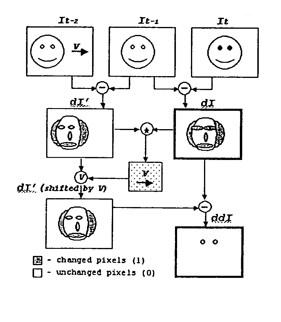
[0009]The present invention relates to methods and devices for processing captured video frames to detect specific changes observable in video using three consecutive video frames. The images in the first video frame are compared with the second frame and the images of the second frame are compared with the third frame to produce two intermediate images which show the first order change observable in video. These interim images are then analyzed. A geometric transformation is found such that when the transformation is applied to one of these intermediate images, the number of pixels which match between the interim is maximized. This geometric transformation, which may include a linear as well as a rotational component, is then applied to one of the intermediate images to result in a transformed image. The transformed image is then subtracted from the other intermediate image to arrive at an end image which shows the second order change or the change in a change observable in video. The second order change image will show only those specific pixels which have changed in the images between the three original video frames. The invention may be used to detect changes in the state of a subject's eyes. A subject's blinking can thus be used for sending binary commands to a computer remotely. In particular, a double blink, i.e., two consecutive blinks, of a person can be used as a hand-free substitute to a clicking of a mouse.
[0017](g) determining a geometric transformation such that when said geometric transformation is applied to said second intermediate image, an overlap between images in said first intermediate image and images in said second intermediate image is maximized;

Problems solved by technology

Unfortunately, all of the above interfaces are inaccessible to people who are incapable of physically manipulating such interfaces.
While some speech driven interfaces are available, these are far from ideal.
Navigating a graphical user interface using speech can be quite difficult and “training” the software to recognize the users voice patterns and commands is time consuming.
While head-tracking technologies such as the Nouse show promise, they still have one drawback that makes them fall short of the mouse in terms of ease of use.
However, detecting eye based binary commands, such as blinks and double-blinks, have previously proved difficult and results have been poor.
One major problem has been the difficulty in determining how to locate a person's eyes when his face moves.
Given the non-static nature of the human head, this is not a trivial problem and previous attempts to solve it has met with, at best, mixed results.
Such a drawback limits the usability of such head-tracking methods and technologies.
However, this technique fails to detect eyes when a face moves as many candidates also appear around the face boundary as well as around the nose, mouth, and other parts of the face.

Method used


Image

  • Second order change detection in video
  • Second order change detection in video
  • Second order change detection in video

Examples


Embodiment Construction

[0029]As is well-known, one problem with detecting a change in the open or closed state of eyes in successive video frames is finding which change in the image is caused by eye lid motion and which is caused by head motion. Since the human head is moving, even minutely, between frames, there are frequently elements in the image which have changed because of head motion, such as around brows, lips, nostrils, as well as around the hair line and head boundary. Changes caused by eye lid motion will be easier to detect if those changes caused by head motion, which may be referred to as global changes, can be detected and removed from the consideration.

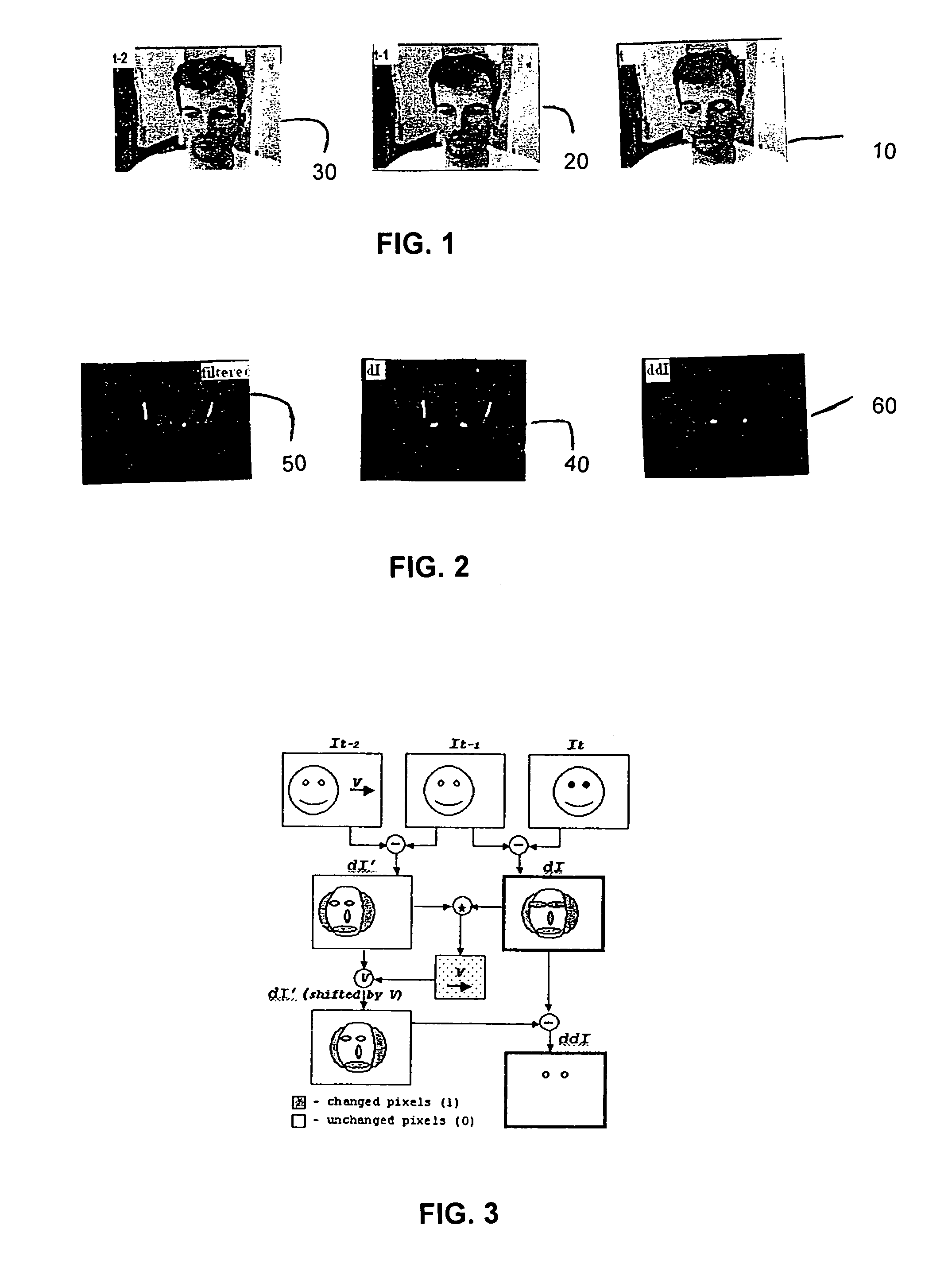
[0030]The above detection and removal from consideration of global changes can be done by using at least three successive video frames. Referring to FIG. 1, three successive video frames are illustrated with the subject of the frames closing his eyes in the first frame 10. As can be seen, between the third frame 30 and the second frame 20, ...


PUM


Abstract

Methods and devices for processing captured video frames to detect specific changes observable in video using three consecutive video frames. The images in the first video frame are compared with the second frame and the images of the second frame are compared with the third frame to produce two intermediate images which show the first order change observable in video. These interim images are then analyzed. A geometric transformation is found such that when the transformation is applied to one of these intermediate images, the number of pixels which match between the interim is maximized. This geometric transformation, which may include a linear as well as a rotational component, is then applied to one of the intermediate images to result in a transformed image. The transformed image is then subtracted from the other intermediate image to arrive at an end image which shows the second order change or the change in a change observable in video. The second order change image will show only those specific pixels which have changed in the images between the three original video frames. The invention may be used to detect changes in the state of a subject's eyes. A subject's blinking can thus be used for sending binary commands to a computer remotely. In particular, a double blink, i.e., two consecutive blinks, of a person can be used as a hand-free substitute to a clicking of a mouse.

Description

FIELD OF THE INVENTION[0001]The present invention relates to video image processing and, more specifically, relates to but is not limited to methods and devices for determining minute changes occurring between consecutive video frames.BACKGROUND TO THE INVENTION[0002]The field of human-computer interfaces is a growing one. From the evolution of the keyboard to the invention of the mouse, newer and better means for interacting with computers have always been sought. One seeming constant in past and current interfaces has been the requirement for human hands, digits, or other physical appendages to manipulate some sort of implement to interact with a computer. Keyboards, mice, light pens, track balls and other human-computer interfaces all require human interaction and physical manipulation of at least some part of the interface.[0003]Unfortunately, all of the above interfaces are inaccessible to people who are incapable of physically manipulating such interfaces. While some speech dr...

Claims


Application Information

Patent Timeline
Patent Type & Authority Patents(United States)
IPC IPC(8): G06K9/00G06F3/01G06T7/20H04N7/00
CPCG06F3/013G06T7/2053G06T7/254
Inventor GORODNICHY, DMITRY O.
Owner NAT RES COUNCIL OF CANADA
Learn More