Method and apparatus for correction of mammograms for non-uniform breast thickness

a mammogram and non-uniform technology, applied in the field of medical imaging, can solve problems such as reducing the accuracy of abnormal detection

Inactive Publication Date: 2007-04-10
HOLOGIC INC
View PDF16 Cites 19 Cited by
  • Summary
  • Abstract
  • Description
  • Claims
  • Application Information

AI Technical Summary

Benefits of technology

[0006]A method and apparatus for correcting for a distortion in a mammogram. The method comprises classifying pixels as either likely fat or likely not-fat. The method further comprises identifying a candidate distortion and calculating a histogram of the likely fat and the likely not-fat pixels at the can

Problems solved by technology

Such a change in the relative color of the imag

Method used


Image

  • Method and apparatus for correction of mammograms for non-uniform breast thickness
  • Method and apparatus for correction of mammograms for non-uniform breast thickness
  • Method and apparatus for correction of mammograms for non-uniform breast thickness

Examples


Embodiment Construction

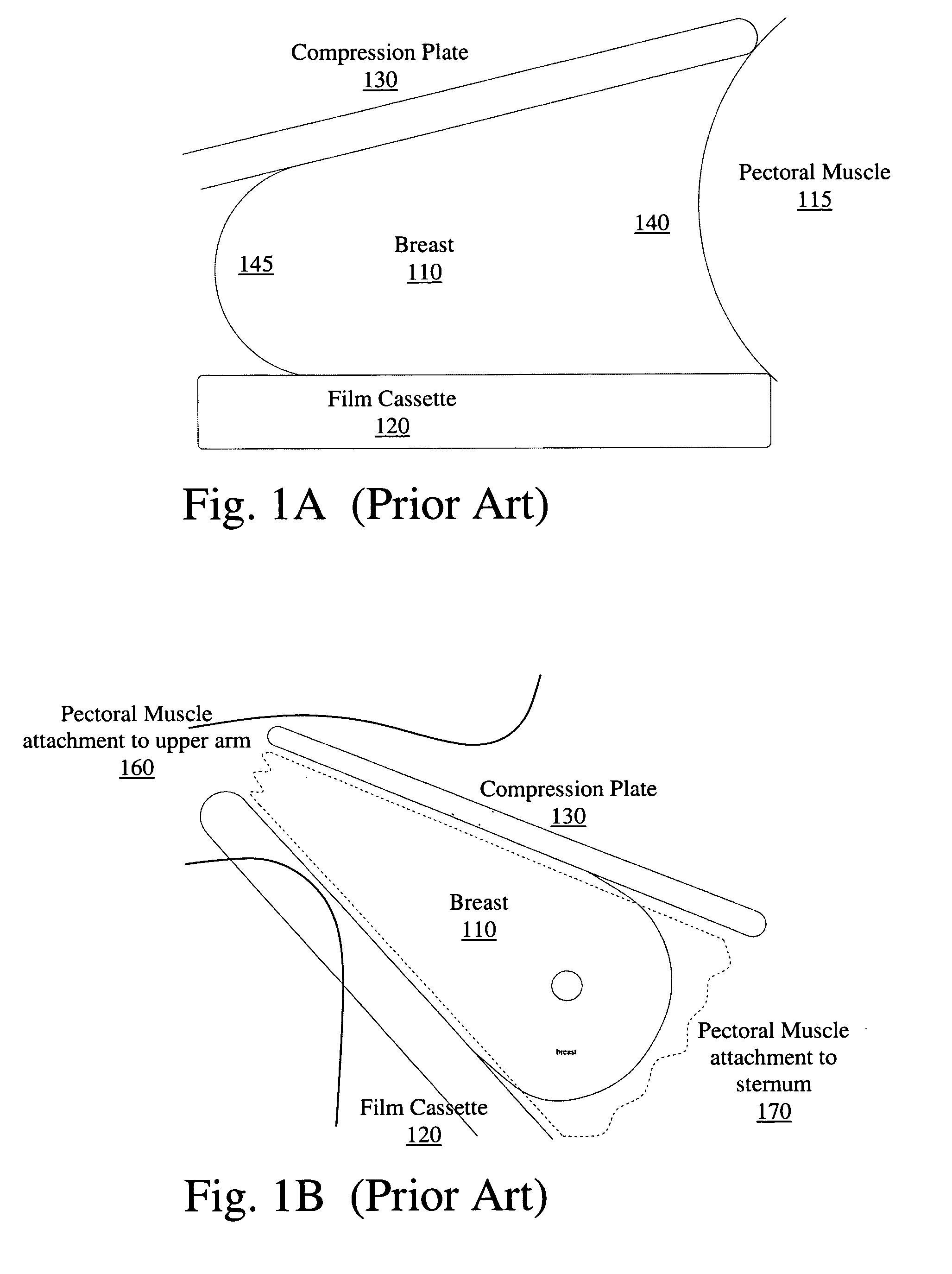
[0020]A method and apparatus for correcting distortion in a mammogram image is described. Such a distortion may be introduced by a tilt in the plates used to take a mammogram, or a bend or other distortion in the plates. For simplicity, the case of a tilt will be discussed in greater detail herein. However, one of sill in the art would be able to send this to a non-linear correction, such as a 2nd order correction.

[0021]The relative tilt between the compression plates when a mammogram is acquired introduces a trend that tends to make pixel values change predictably across the breast. Given that pixel value in log (exposure) images varies roughly linearly with the line integral of density between the pixel and the focal spot of the X-ray tube, it can be assumed that tilt between the compression plates appears as a linear trend in pixel value depending on position in the image plane. This trend is most obvious in the intensities of pixels that are covered by almost pure fat between th...


PUM


Abstract

A method and apparatus for correcting for a distortion in a mammogram. The method comprises classifying pixels as either likely fat or likely not-fat. The method further comprises identifying a candidate distortion and calculating a histogram of the likely fat and the likely not-fat pixels at the candidate distortion. The method further comprises evaluating a quality of the candidate distortion based on features of the histograms of pixel values in the fat and dense tissue classes. The distortion may be a two dimensional tilt of the plates or a three dimensional deformation of the plates as in a bend.

Description

FIELD OF THE INVENTION[0001]The present invention relates to medical imaging, and more specifically, to tilt correction in a mammogram.BACKGROUND[0002]Mammograms are generally obtained by pressing the breast between two plates of imaging radiation transparent material, and taking an image of the compressed breast tissue. The image may be X-ray or another type of image. In theory, the two plates should be parallel to take a perfect quality picture. However, in reality, the pectoral muscle and tissue inhomogeneity affect the shape of the compressed breast, by keeping the two plates from being parallel.[0003]FIG. 1A illustrates one example of the breast tissue 110 compressed between the film cassette 120 and compression plate 130 from the cranial caudal view. As can be seen, the two plates 120, 130 are not parallel. This results in a lighter 140 and darker 145 region of the image.[0004]Similarly, FIG. 1B illustrates the mediolateral oblique view of the compressed breast, showing that t...

Claims


Application Information

Patent Timeline
IPC IPC(8): G06K9/00
CPCG06T5/006G06T2207/30068
Inventor KARSSEMEIJER, NICOLAASSCHNEIDER, ALEXANDER CALDWELL
Owner HOLOGIC INC
Why Eureka
Try Eureka