Hinge

a hinge and hinge technology, applied in the field of hinges, can solve the problems of difficulty in achieving both objectives, and achieve the effects of reducing the difficulty of adjusting the hinge, increasing the strength of the hinge, and increasing the mechanical advantag

Active Publication Date: 2007-04-17
MORGAN WILLIAM D
View PDF43 Cites 19 Cited by
  • Summary
  • Abstract
  • Description
  • Claims
  • Application Information

AI Technical Summary

Benefits of technology

[0004]The hinge of the present invention addresses this problem by using a mechanism that causes the joined objects, when being swung away from the close-together position, to also move slightly apart from one another as they pivot. By moving the opposed faces of the two hinged-together objects apart as the objects swing away from the close-together position, there is less need of a clearance gap when in the close-together position. To accomplish this simultaneous translation and pivoting movement, the hinge of the present invention comprises:
[0012]Each pin slidably engages one of the guide slots and the pair of pins can simultaneously slide in their respective guide slots. Since the guide slots of each pair of slots are non-parallel, when one pin is forced to slide in one direction, the first assembly is forced to both turn and translate with respect to the link. Thus, if the hinge is at its close-together position and a turning force is applied to the first assembly, the first assembly will not only swing out of that plane, it will also shift to the side, putting more distance between the two objects that are hingedly joined together.
[0020]Although the two guide slots in each pair are angled toward each other, preferably the slots themselves do not intersect. In this way, there can be smooth, uninterrupted boundary walls for the pins to slide against. It is also preferred that at least those portions of the slots that guide the pins through the first 90 degrees of swing from the close-together position be substantially straight.
[0024]To add strength to the hinge, it is preferred that there be a first projection extending from one end of the link and that the first assembly comprise a first end plate having a stop slot that cooperates with that projection. There is preferably also a tab that protrudes from each member of the pair of second side plates, in combination with slots in each lateral side of the link. With the first assembly being pivotable relative to the link between an extended position and a folded position, these elements are so arranged that further pivoting of the first assembly relative to the link beyond the extended position is limited by abutment of the first projection of the link against the stop slot of the first end plate (at a first “stop point”) and / or by abutment of the notch in each lateral side of the link against the tab of each of the first side plates (at a second stop point). In this arrangement, the stress on the hinge is concentrated at the stop points, rather than the pins, when the leaf is in the extended position. This provides the hinges with a greater mechanical advantage and distributes the resulting stresses over a larger area than the pins. Accordingly, the hinge is able to support greater loads. For example, when a hinge according to my invention is used in a fold-over / drop-leaf table, each hinge is able to support loads in excess of 100 pounds applied to the leaf at a distance of ten inches from the hinge center of the hinge. Such high loads may be present when, for example, a person presses down on the leaf while either rising from the table or stretching across it in order to inspect something resting on the other side.

Problems solved by technology

But if the leaf is to fold onto the top of the table, it is difficult to accomplish both objectives: positioning the hinge pins below the upper surface and having little or no gap between the top and the leaf when in the coplanar position.

Method used


Image

  • Hinge
  • Hinge
  • Hinge

Examples


Embodiment Construction

)

[0038]FIGS. 1–7 depict one embodiment of the present invention, with FIGS. 5A and 5B showing two different types of pin restrainers that can be used.

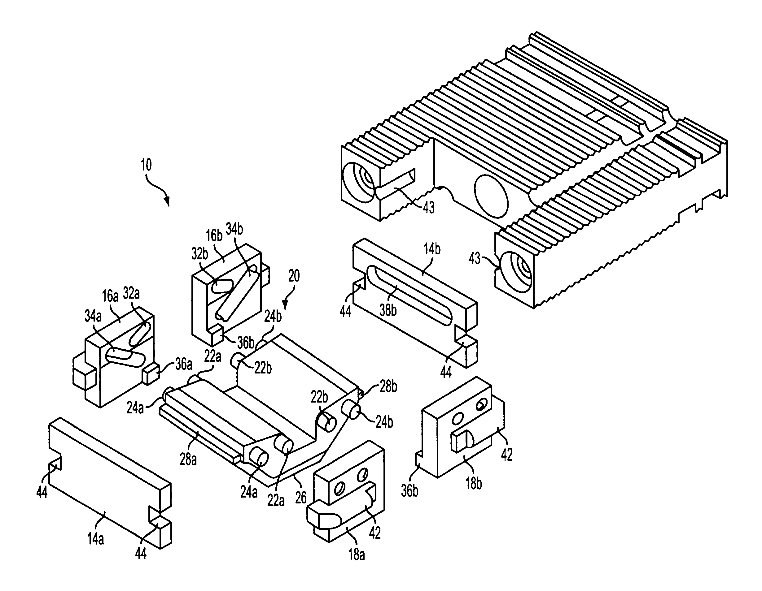
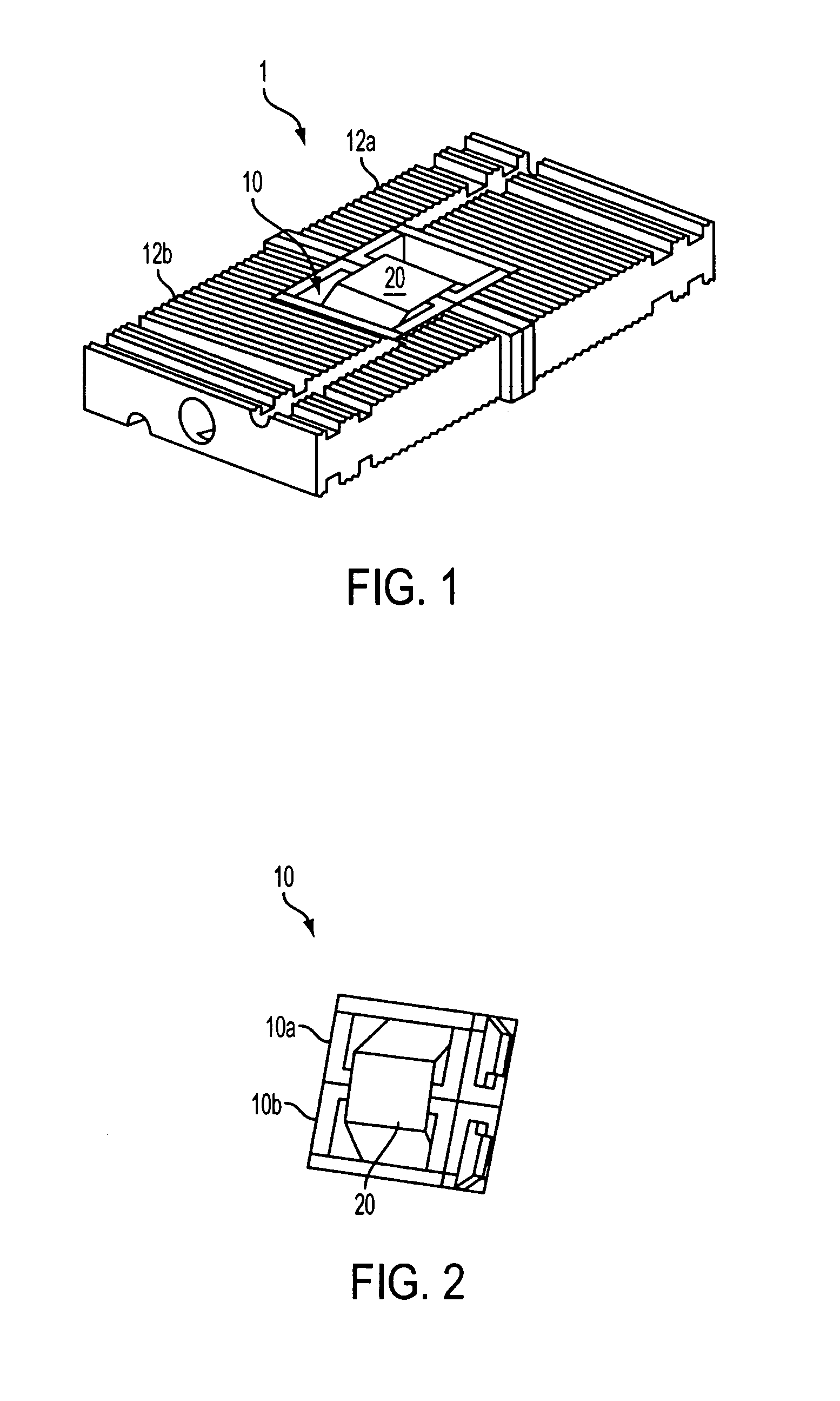
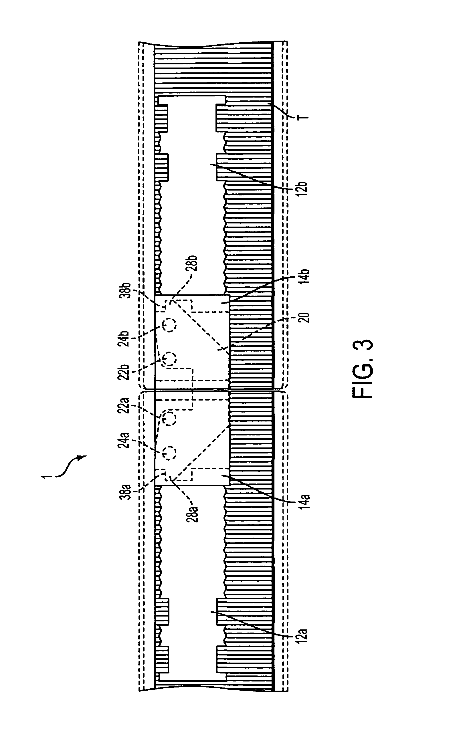
[0039]As shown in FIGS. 1 and 2, hinge cage 10 connects mounting members 12a and 12b. Hinge cage 10 comprises a center link 20 disposed between and pivotally connecting first and second cage portions 10a and 10b (the components of hinge cage 10 are shown in more detail in FIG. 4). The first and second cage portions 10a and 10b are mounted in first and second mounting members 12a and 12b, respectively. The mounting members 12a and 12b can be made of a variety of materials, but in the preferred embodiment are made from 6061 T6511 aluminum. Hinge assembly 1 allows the mounting members 12a and 12b to pivot 180 degrees relative to one another about two dynamic axes of rotation. By “dynamic” it is meant that the axes of rotation move slightly away from each other during the operation of the hinge.

[0040]FIG. 3 is a cross-sectional view of the...


PUM


Abstract

A hinge includes a link with two lateral sides, and an assembly comprising a pair of side plates. Protruding from each lateral side of the link is a pair of parallel pins, and each side plate includes a pair of non-parallel guide slots. The assembly and the link are positioned such that each pin slidably engages one of the guide slots and the pins can simultaneously slide in their respective guide slots. Since the guide slots are non-parallel, when one pin is forced to slide in one direction, the other pin of the pair is forced to slide in a different direction, causing the assembly to both turn and translate with respect to the link.

Description

FIELD OF THE INVENTION[0001]The present invention relates to a type of hinge that can be used for, among other things, attaching a table leaf to a table top in a drop-leaf table in which the leaf, when not extended, is folded onto the top of the table (a “fold-over / drop-leaf table”).BACKGROUND OF THE INVENTION[0002]As described in my prior patent, U.S. Pat. No. 4,928,350, in certain hinge applications it is desirable for the hinge to allow the two objects it joins to be so close together when the hinge is at a certain position in its swing path that there is little or no gap between the objects. An example is a drop-leaf table. When the leaf and the table top are in the coplanar position—i.e., the leaf is extended—it is preferred that there be little or no gap between them.[0003]Often in such drop-leaf table applications it is also preferred that no part of either hinge extend above the top and leaf when in the coplanar position—i.e., that the extended table top be smooth and uninte...

Claims


Application Information

Patent Timeline
Patent Type & Authority Patents(United States)
IPC IPC(8): E05D11/06E05D15/00
CPCE05D3/18Y10T16/5475Y10T16/5443E05D11/06
Inventor MORGAN, JAMES C.
Owner MORGAN WILLIAM D
Why Eureka
Try Eureka