Tiller, bow and trigger mechanism for a crossbow, and a crossbow

a crossbow and trigger mechanism technology, applied in bows/crossbows, white arms/cold weapons, weapons, etc., can solve the problems of limiting the maximum launch force and significantly increasing production costs, and achieve the effects of convenient handling and transportation, convenient mounting or removal, and fast assembling and dismantling of the crossbow

Inactive Publication Date: 2007-04-17
RAVIN CROSSBOWS
View PDF13 Cites 53 Cited by
  • Summary
  • Abstract
  • Description
  • Claims
  • Application Information

AI Technical Summary

Benefits of technology

[0018]Such a trigger mechanism is sturdy but simultaneously it has a high sensitivity, and thus requires a minimal force to release the bowstring for shooting a projectile. It provides also a high safety, as the trigger mechanism is easily protected against self-release by blocking the working element (ball) of a counterrecoil mechanism.
[0021]Due to the modular construction of the bow it can be readily mounted on or removed from the tiller, which enables fast assembling and dismantling of the crossbow. This makes it very convenient for handling and transporting. Furthermore the structure of the bow results in the substantial reduction of the kick effect and diminishes the impact of inertial force on the person shooting the crossbow.
[0022]Furthermore the bow of the invention has a distinct advantage in that it can be up to 50% narrower than various conventional bows, and yet it still ensures exceptionally good cocking parameters. The structure of the bow, and in particular its pivotal connection about the bolts, provides for considerable reduction of friction between the bowstring and the projectile guide when the bowstring is drawn.
[0023]The structure of the modular parts of the crossbow, i.e. of the tiller and the bow, makes it possible to assembly a compact crossbow of a small width, easy to cock with a minimal effort, yet providing a large draw force. The crossbow is fast-firing and allows for discharging projectiles with a high initial velocity.

Problems solved by technology

In this known cocking mechanism the crank lever is relatively short which limits possible maximum launch force.
To eliminate any movement of the projectile guide in relation to the aiming device in this known crossbow extremely precise dimensional tolerances must be strictly observed during its manufacturing, which significantly increases production costs.

Method used


Image

  • Tiller, bow and trigger mechanism for a crossbow, and a crossbow
  • Tiller, bow and trigger mechanism for a crossbow, and a crossbow
  • Tiller, bow and trigger mechanism for a crossbow, and a crossbow

Examples


Embodiment Construction

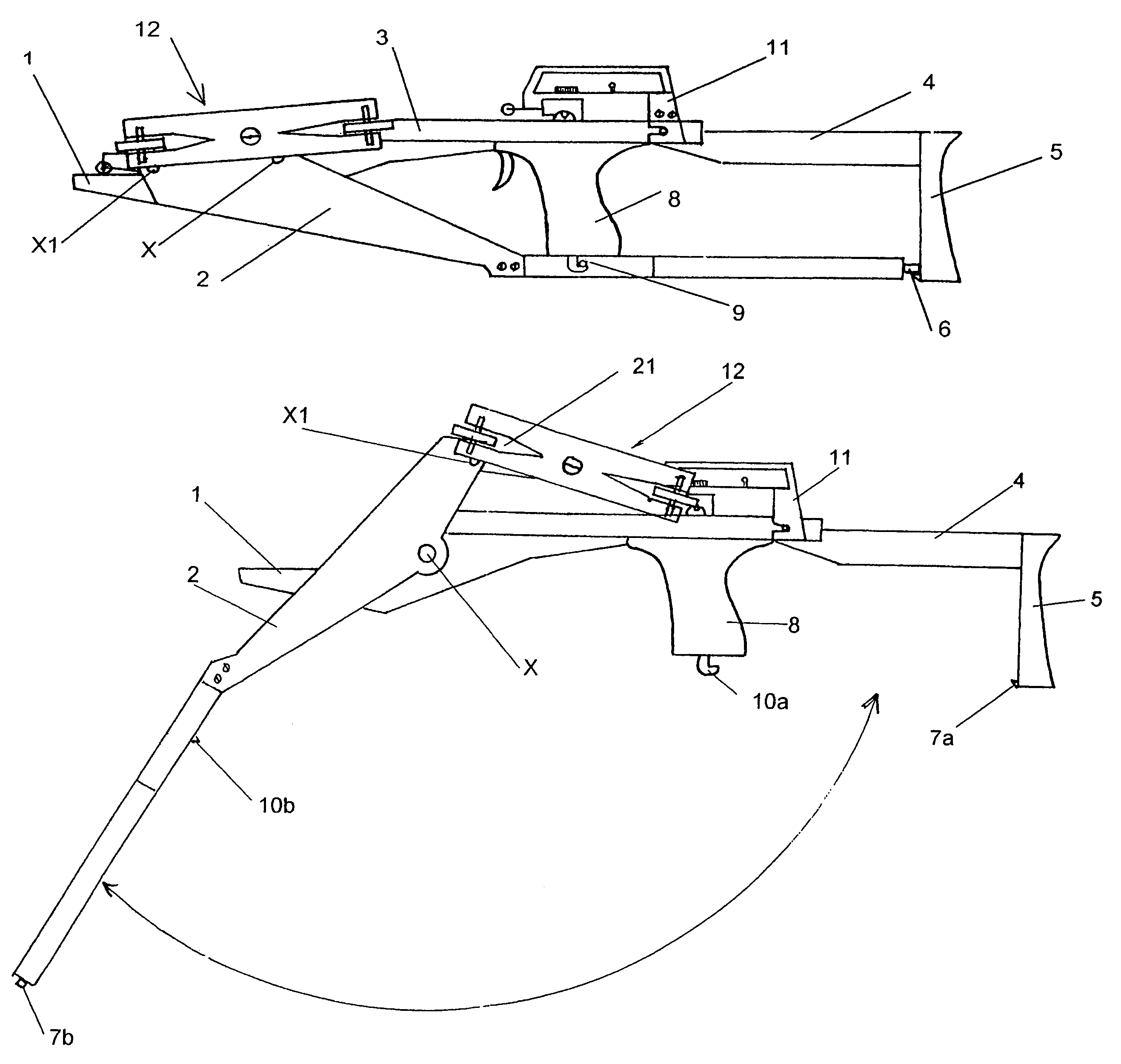
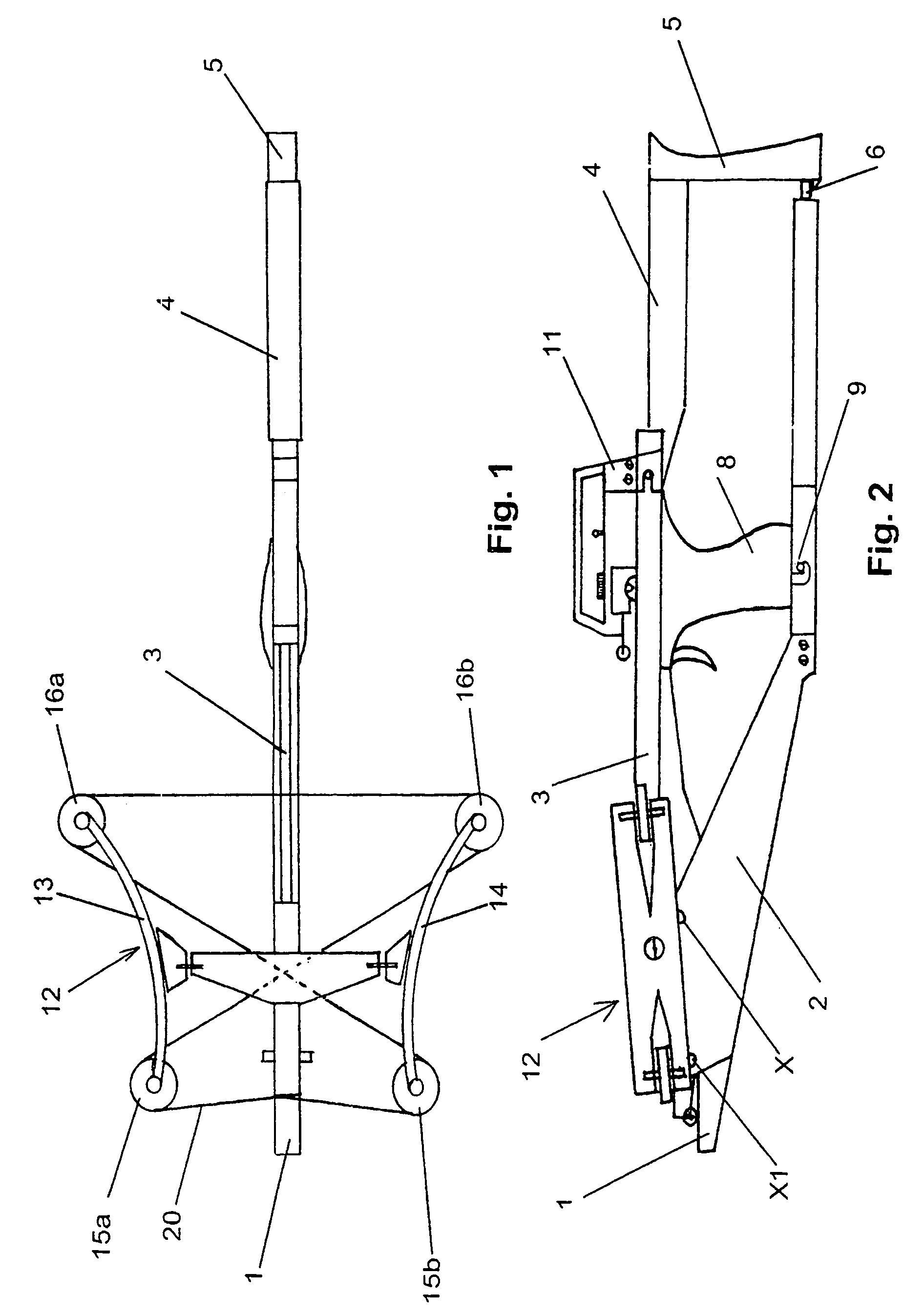
[0038]FIG. 1 shows a crossbow of the invention in its uncocked state with its tiller folded and snapped, as described below.

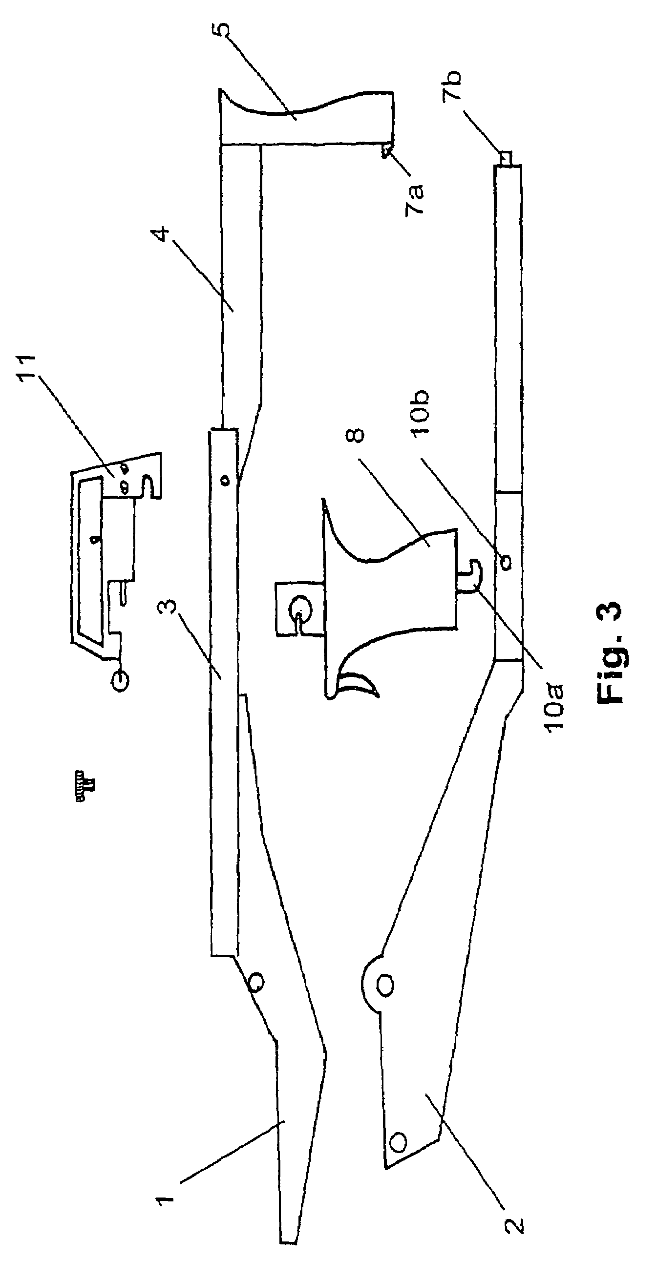
[0039]FIGS. 2, 3 and 4 show the crossbow of FIG. 1, folded, disassembled (only the tiller, aiming device and trigger portion are shown) and unfolded respectively.

[0040]The tiller on which the bow (12) is mounted has a cocking lever in the form of two arms, an upper arm 1 and a lower arm 2, which are pivotably connected about an axis X in the front part of the tiller.

[0041]The upper arm 1 has a projectile guide 3 which abuts a butt bracket 4 through which the upper arm 1 is connected with the butt 5 in the rear part of the tiller.

[0042]The upper arm 1 is connected with the upper end of a butt 5, and said lower arm 2 is connected in the folded state of the tiller with the lower end of the butt 5 by means of a rear snap fastener 6. The rear snap fastener 6 is formed by a finger 7a on the butt 5 and a hook 7b at the end of the lower arm 2.

[0043]A trigger mechanism ...


PUM


Abstract

The invention relates to a tiller for a crossbow which has a cocking lever in the form of an upper arm (1) and a lower arm (2) pivotally connected with each other about an axis (X) in the front part of the tiller, whereas in the rear part of the tiller said upper arm (1) is connected with the upper end of a butt (5), and said lower arm (2) is connected with the lower end of the butt (5) in the folded state of the tiller by means of a snap fastener (6). Said tiller for a crossbow can be assembled with any appropriate bows and trigger mechanisms, but preferably it is used with a novel bow for a crossbow which is also disclosed.

Description

BACKGROUND OF THE INVENTION[0001]The invention relates to a tiller and bow for a crossbow, and to a crossbow containing at least one of the aforementioned parts.[0002]Crossbows having a bow (or prod) equipped with pulleys for a bowstring mounted on a tiller provided with a butt, trigger mechanism and aiming device, cocked by means of various cocking mechanisms, have been known for long time.[0003]EP 0 132 017 B1 discloses a crossbow having a tiller which carries a prod and a bowstring arrestor, and having a release mechanism. Said prod is mounted for reciprocal movement relative to the tiller to facilitate cocking the bow. The crossbow is cocked with the use of a cocking mechanism comprising a crank lever which has one of its ends pivotally mounted to the stock by means of a stock pin and has its opposite end pivotally connected between the ends of a connecting lever by means of a crank pin. The “slider” of the cocking mechanism comprises a draw block to which one end of the connect...

Claims


Application Information

Patent Timeline
Patent Type & Authority Patents(United States)
IPC IPC(8): F41B5/12F41B5/00
CPCF41B5/12F41B5/1469
Inventor DZIEKAN, MARCIN
Owner RAVIN CROSSBOWS
Why Eureka
Try Eureka