High brightness light emitting diode

a light-emitting diode and high-brightness technology, applied in the direction of semiconductor devices, electrical apparatus, transistors, etc., can solve the problems of unsatisfactory uniformity of mixture, and achieve the effects of high brightness (hb), high brightness light, and uniform distribution

Active Publication Date: 2007-04-17
UNITY OPTO TECH CO LTD +1
View PDF2 Cites 8 Cited by
  • Summary
  • Abstract
  • Description
  • Claims
  • Application Information

AI Technical Summary

Benefits of technology

[0003]Thus, a primary objective of the present invention is to provide a high brightness (HB) light emitting diode (LED), comprising a reflector cap for supporting LED dices of different colors and providing primary mixture of the lights from the LED dices and a lens having depending projections fit over the cap for performing secondary mixture over the lights from the LED dices whereby uniform distribution of high brightness light can be realized.
[0004]Another objective of the present invention is to provide a high brightness light emitting diode comprising a lens forming projections for stably mounting the lens over a reflector cap that supports LED dices and defining gas expelling openings through which gas inside the cap can be effectively expelled when plastic packaging is performed over the LED.
[0005]To achieve the above objective, in accordance with the present invention, a high brightness light emitting diode (LED) comprising a base, a reflector cap, a plurality of LED dices, a plastic layer, a lens, and a silicon rubber layer. Conductive terminals extend from the base for connection with an external power source. The base defines a bore receiving and retaining the cap with a bottom of the cap exposed in the bottom of the base. The cap forms a cavity receiving and fixing the LED dices, which are electrically connected to the conductive terminals. The plastic layer comprising PPA, LCP, or engineer plastics is filled in the cavity o with ends of the terminals extending beyond the plastic layer. The lens is positioned over the plastic layer and has projections that snugly fit over and engage the base. The silicon rubber layer is interposed between the lens and the base. With such an arrangement, lights from the LED dices can be mixed twice for enhanced uniformity of brightness of the light distribution.

Problems solved by technology

Although mixture of the lights of different colors can be done in such a conventional construction, such mixture is not satisfactorily uniform.

Method used


Image

  • High brightness light emitting diode
  • High brightness light emitting diode
  • High brightness light emitting diode

Examples


Embodiment Construction

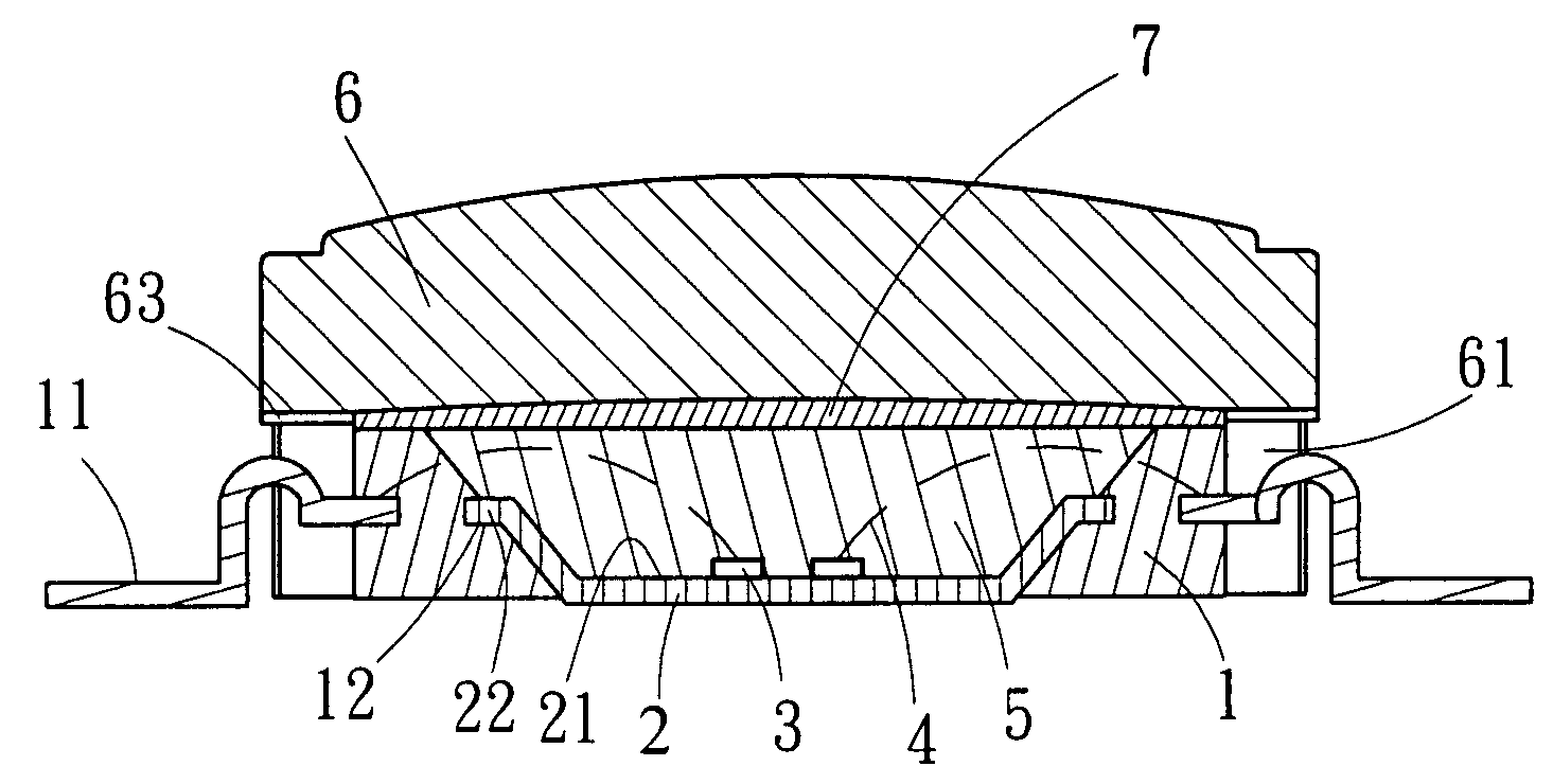
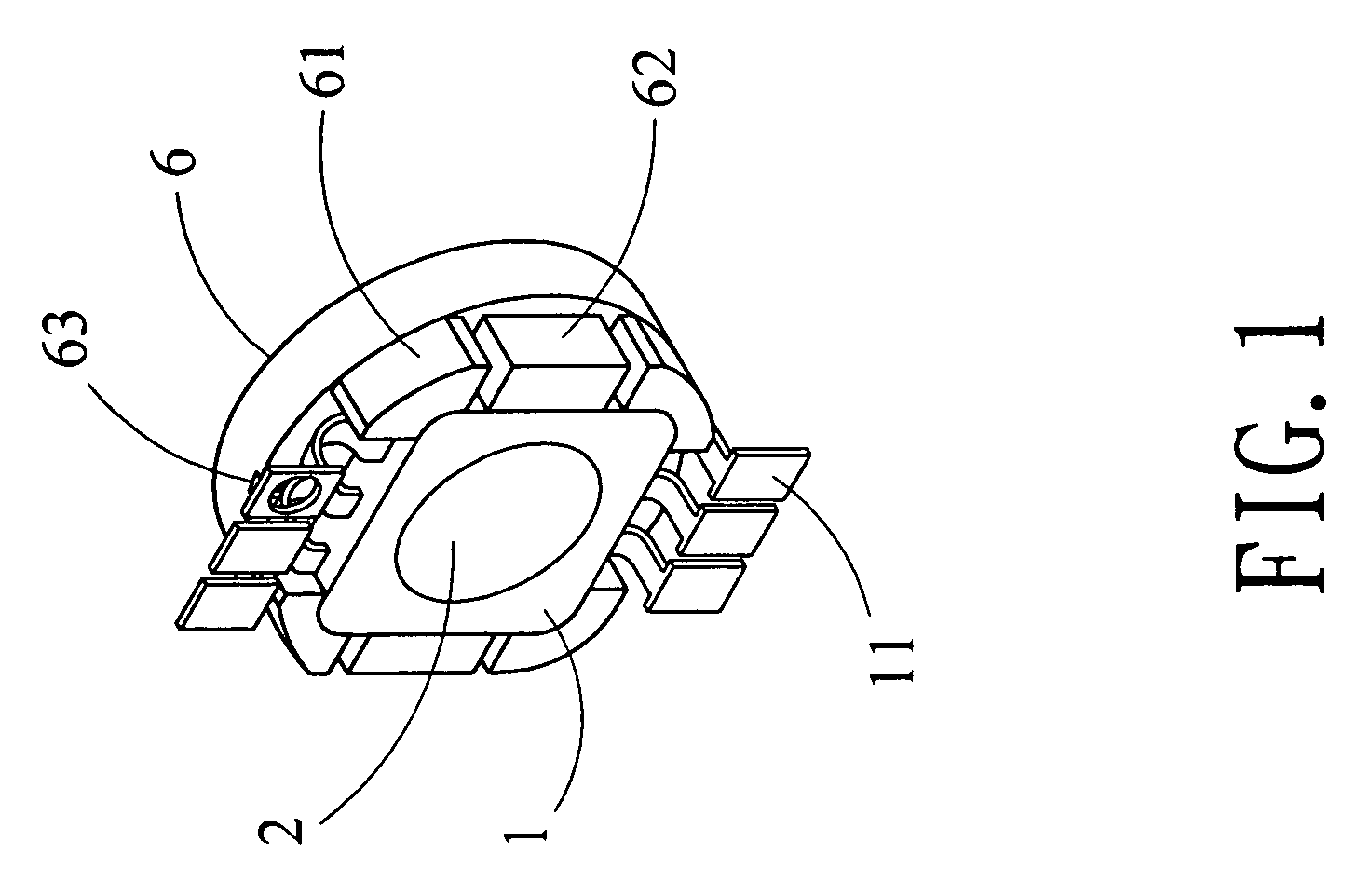
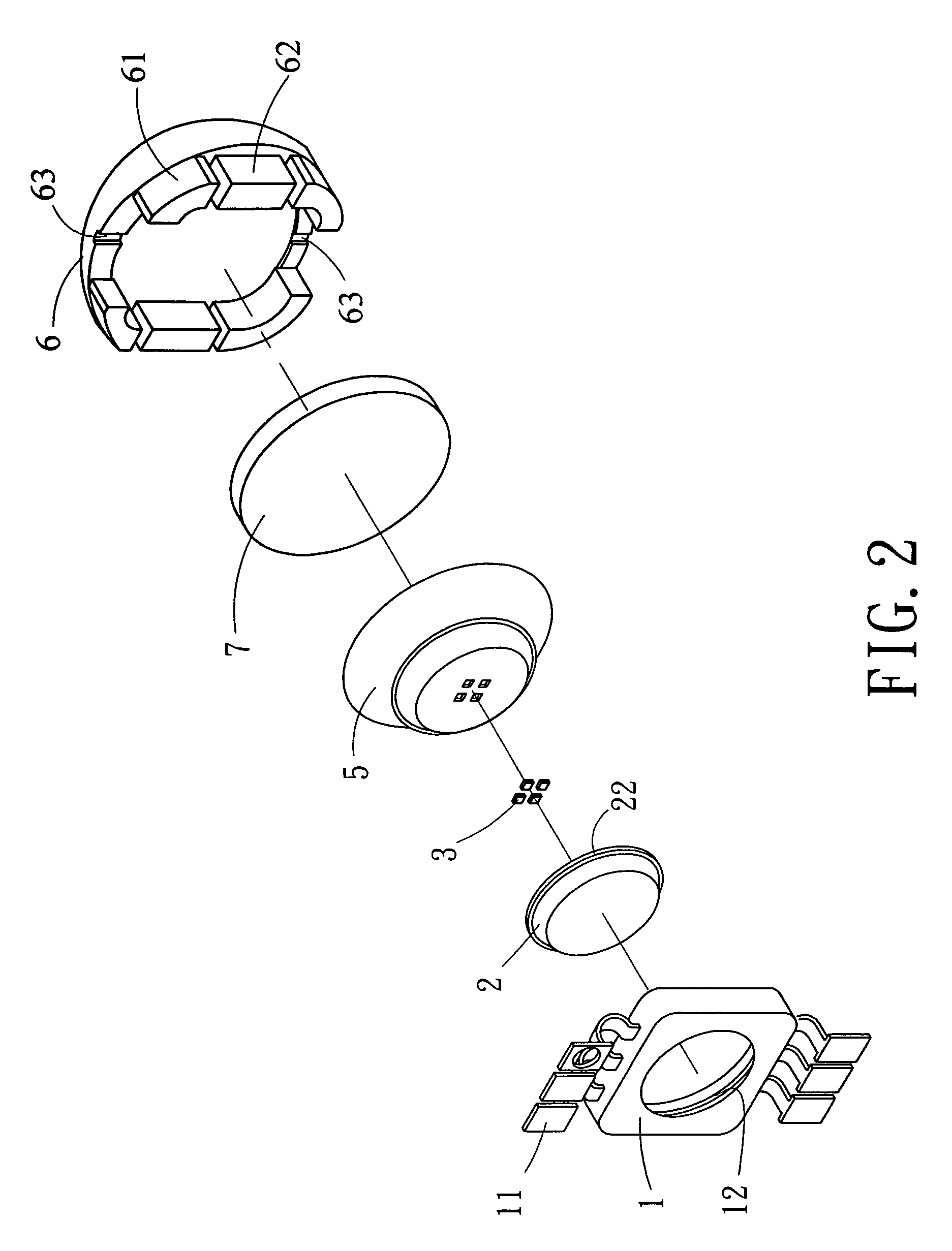
[0012]With reference to the drawings and in particular to FIGS. 1–3, a high brightness (HB) light emitting diode (LED) constructed in accordance with the present invention comprises a base 1 having opposite edges (not labeled) from which conductive terminals 11 extend for connection with an external power source (not shown). The base 1 forms a bore (not labeled) having a circumferential side wall in which a circumferentially extending groove 12 is defined.

[0013]A reflector cap 2 is received in the bore of the base 1 with a bottom of the cap 2 exposed in a bottom surface of the base 1. The cap 2 forms a cavity 21 circumferentially surrounded by an inclined side wall from which a circumferential flange 22 extend. The flange 22 is received in and engages the groove 12 to secure the cap 2 in the bore of the base 1. The cap 2 can be made of ceramics, plastics or metals, which allows for reflection of light.

[0014]The HB LED comprises a plurality of LED dices 3, which give off lights of di...


PUM


Abstract

A high brightness light emitting diode (LED) includes a base, a reflector cap, LED dices, a plastic layer, a lens, and a silicon rubber layer. Conductive terminals extend from the base for connection with an external power source. The base defines a bore receiving the cap with a bottom of the cap exposed. The cap forms a cavity receiving the LED dices, which are electrically connected to the conductive terminals. The plastic layer comprising PPA, LCP, or engineer plastics is filled in the cavity o with ends of the terminals extending beyond the plastic layer. The lens is positioned over the plastic layer and has projections that snugly fit over and engage the base. The silicon rubber layer is interposed between the lens and the base. With such an arrangement, lights from the LED dices can be mixed twice for enhanced uniformity of brightness of the light distribution.

Description

FIELD OF THE INVENTION[0001]The present invention generally relates to a high brightness light emitting diode (HB LED), and in particular to an LED comprising a plurality of different color LED dices positioned in a reflector cap that provides primary mixture of color lights from the LED dices and a lens having projections fit over the reflector cap to provide secondary mixture of the color lights whereby a uniform distribution of high brightness light can be obtained for better utilization in wide applications of different lighting requirements, such as lighting for shopping malls, lighting for exhibition, lighting for advertisement boards, as well as a variety of lighting devices, and backlight devices.BACKGROUND OF THE INVENTION[0002]A conventional light emitting diode (LED), such as that shown in FIG. 5 of the attached drawings, comprises a base 8 having opposite edges from which conductive terminals 81 extending for connection with an external power source. The base 8 defines a...

Claims


Application Information

Patent Timeline
Patent Type & Authority Patents(United States)
IPC IPC(8): H01L29/24
CPCH01L33/486H01L33/60H01L33/62H01L25/0753H01L2224/48091H01L2224/48247H01L2924/3025H01L2924/00014H01L2924/00
Inventor CHIN, YUAN-CHENGLI, HUNG-CHIH
Owner UNITY OPTO TECH CO LTD
Why Eureka
Try Eureka