
Method of hydraulic fracturing to reduce unwanted water production

a technology of hydraulic fracturing and unwanted water, applied in the direction of fluid removal, chemistry apparatus and processes, borehole/well accessories, etc., can solve the problems of undesirable fracture height growth and inability to provide satisfactory solutions to unwanted water production

Active Publication Date: 2007-04-24
BAKER HUGHES HLDG LLC
View PDF43 Cites 79 Cited by
  • Summary
  • Abstract
  • Description
  • Claims
  • Application Information

AI Technical Summary

Benefits of technology

[0009]Where the fluid density of the proppant-free fluid is greater than the fluid density of the proppant laden slurry, the method of the invention further limits undesirable fracture height growth in the hydrocarbon-bearing subterranean formation during the fracturing. The fracture, initiated by the introduction of the proppant-free fluid, grows below the productive zone of the formation, the proppant-free slurry migrating to the lower extremities of the initiated fracture by gravity segregation. The density differential of the proppant-free fluid and the proppant laden slurry allows the proppant laden slurry to override the dense proppant-free fluid, thereby causing a separation of the proppant laden slurry from the proppant-free fluid.

Problems solved by technology

Most often, such problem areas are associated with non-productive fracture growth below the zone of productive interest.
Such methods do not however provide a satisfactory solution to the production of unwanted water.
The problem of undesirable fracture height growth may particularly be a problem when practicing slickwater treatments, in light of the poor transport properties of slickwater fluids which allow proppants to settle, forming a “proppant bank” at the bottom of the created fracture.
Unfortunately, such proppant banks in contact with water producing zones often provide a high permeability conduit for unwanted water production.

Method used


Image

  • Method of hydraulic fracturing to reduce unwanted water production
  • Method of hydraulic fracturing to reduce unwanted water production
  • Method of hydraulic fracturing to reduce unwanted water production

Examples


examples

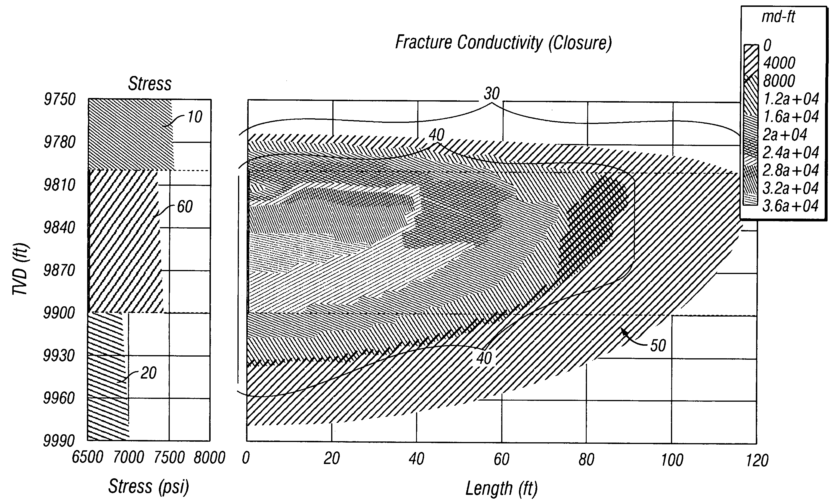
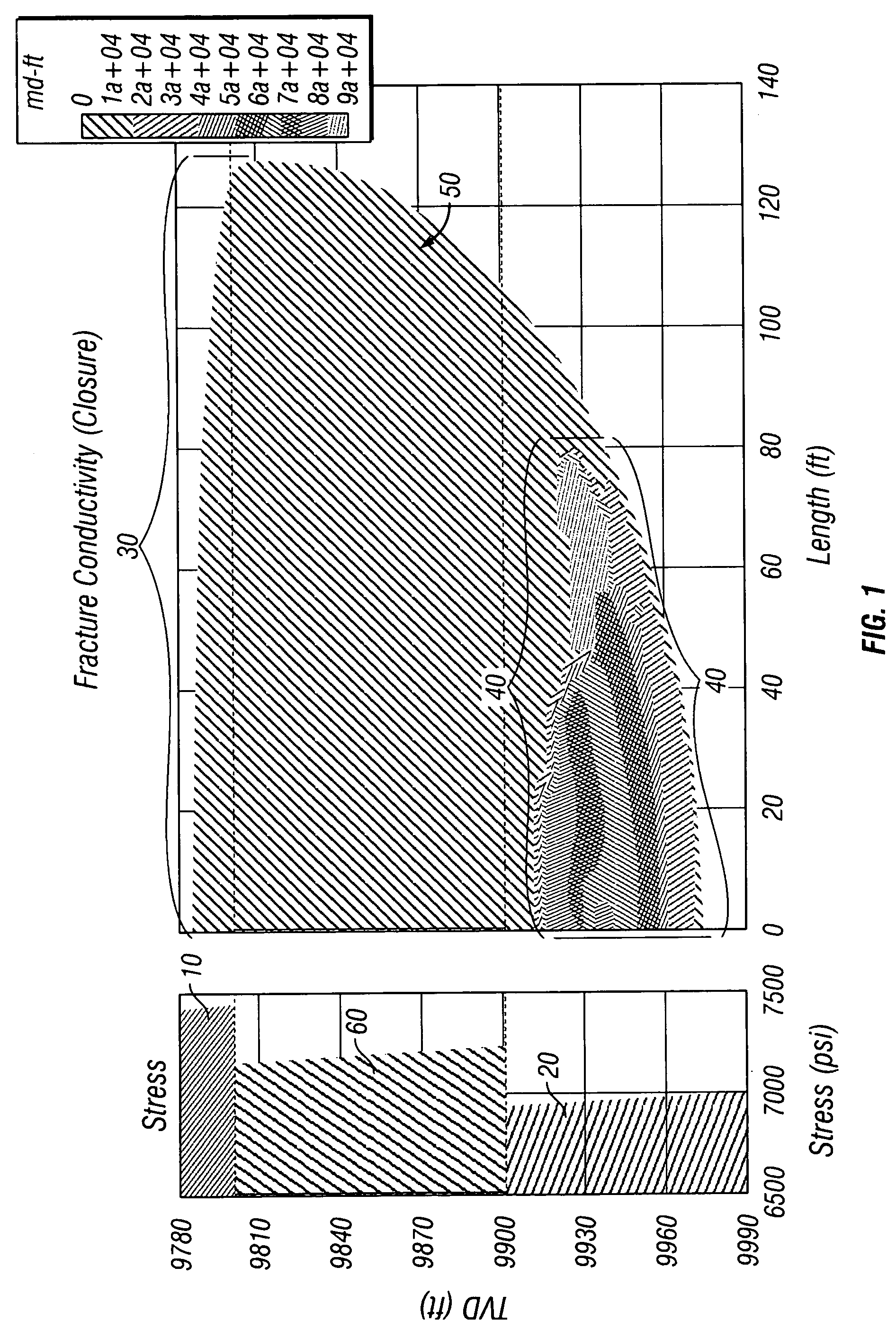
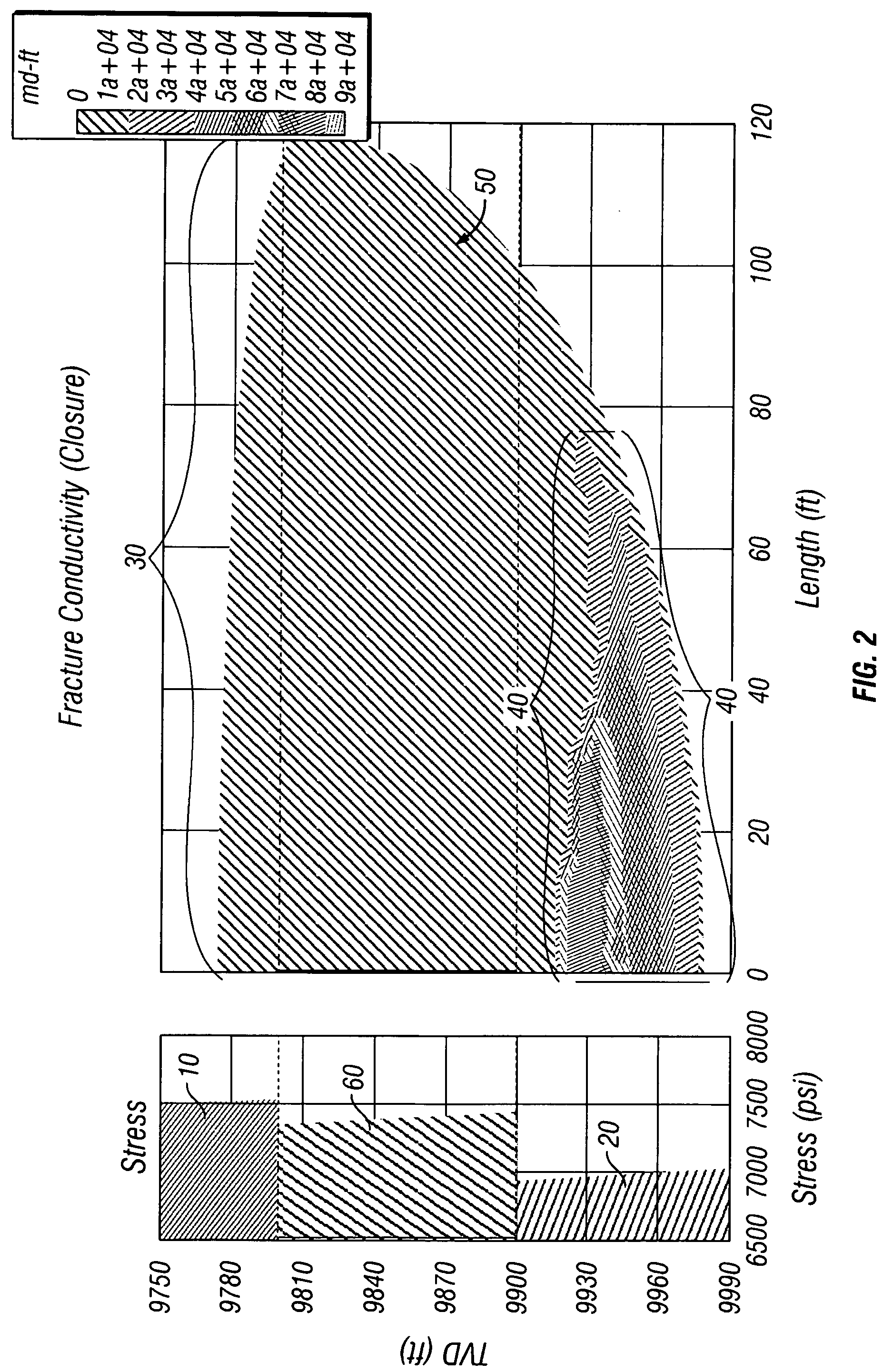
[0053]The Examples demonstrate the ability of the process of the invention to control water production.

[0054]A fracture was simulated using the Mfrac three-dimensional hydraulic fracturing simulator of Meyer & Associates, Inc. using a simple 3-layer isotropic homogeneous 0.1 mD permeability gas reservoir model, 40 acre spacing. The fracture was designed to be placed into the zone at a theoretical depth of approximately 9800 to about 9900 feet and the model was run in full 3-D mode. Since the Mfrac model does not make calculations for a partial monolayer, the conductivity of the proppant was artificially increased at a concentration of 0.5 lbs / sq. ft. at a rate of 50 barrels per minute (bpm).

[0055]Fracture conductivity between the proppant-packed fracture and that of the native reservoir, mathematically defined as:

(proppant pack permeability×fracture width) / (formation permeability×propped fracture half length),

is illustrated in the conductivity profiles of FIGS. 1, 2 and 3 after clos...


PUM


Abstract

A method of hydraulically fracturing a hydrocarbon-bearing subterranean formation ensures that the conductivity of water inflow below the productive zone of the subterranean formation is reduced. The method consists of two principal steps. In the first step, a fracture in and below the productive zone of the formation is initiated by introducing into the subterranean formation a fluid, free of a proppant, such as salt water, fresh water, brine, liquid hydrocarbon, and / or nitrogen or other gases. The proppant-free fluid may further be weighted. In the second step, a proppant laden slurry is introduced into the subterranean formation which contains a relatively lightweight density proppant. Either the fluid density of the proppant-free fluid is greater than the fluid density of the proppant laden slurry or the viscosity of the proppant-free fluid is greater than the viscosity of the proppant laden slurry. The method limits undesirable fracture height growth in the hydrocarbon-bearing subterranean formation during the fracturing.

Description

[0001]This application claims the benefit of U.S. patent application Ser. No. 60 / 480,063, filed Jun. 20, 2003.FIELD OF THE INVENTION[0002]This invention relates to a method of treating subterranean formations and, more specifically, to hydraulic fracturing treatments for subterranean formations. Use of the method of the invention reduces unwanted water production which ordinarily may result during hydraulic fracturing.BACKGROUND OF THE INVENTION[0003]In the production of fluids from subterranean formations, it has been a long-standing practice to hydraulically fracture the formation from a wellbore to enhance the flow of fluids from the formation into the wellbore. Hydraulic fracturing is typically employed to stimulate wells which produce from low permeability formations.[0004]During hydraulic fracturing, a fracturing fluid is injected into the wellbore at high pressures to create fractures in the rock formation surrounding the bore. The fractures radiate outwardly from the wellbor...

Claims


Application Information

Patent Timeline
Patent Type & Authority Patents(United States)
IPC IPC(8): E21B43/267E21B43/26
CPCC09K8/64C09K8/68E21B43/261E21B43/267Y10S507/924
Inventor BRANNON, HAROLD DEANWOOD, WILLIAM DALEPURVIS, DONALD L.RICKARDS, ALLAN RAYSTEPHENSON, CHRISTOPHER JOHN
Owner BAKER HUGHES HLDG LLC
Learn More