Method of manufacturing terminal

a manufacturing method and terminal technology, applied in the direction of coupling device connection, contact member manufacturing, coupling device details, etc., can solve the problems of difficult appearance inspection, solder bridge cannot be removed, and appearance inspection of solder fillets is more difficult to perform, so as to achieve the effect of significantly improving the product accuracy of the first terminal and the second terminal

Inactive Publication Date: 2007-04-24
KK TOKAI RIKA DENKI SEISAKUSHO
View PDF9 Cites 24 Cited by
  • Summary
  • Abstract
  • Description
  • Claims
  • Application Information

AI Technical Summary

Benefits of technology

[0020]In manufacturing the first terminal and the second terminal, the terminals can share the same blank material (thin plate-like body), so that the same die for forming the thin plate-like body can commonly be used for both of the first and the second terminals. Accordingly, the die cost can be reduced.
[0024]As a result, according to the second aspect of the invention, product accuracy of the first terminal and the second terminal can be significantly improved, which is preferable.

Problems solved by technology

Therefore, in the configuration in which the plural upper-level terminals and the plural lower-level terminals are provided in parallel, sometimes the appearance inspection is difficult to perform.
In particular, the solder fillet of the lower-level terminal, which is located closer to the connector housing than the upper-level terminal, is positioned so as to be hidden by the upper-level terminal, and the appearance inspection thereof is more difficult to perform than in the case of the solder fillet of the upper-level terminal.
Further, if the appearance inspection of the solder fillet of the lower-level terminal can be performed, when formation of the solder bridge is detected, the solder bridge cannot be removed.
Therefore, in order to produce these terminals, there is a problem that different dies are required for the lower-level terminal and the upper-level terminal, respectively.

Method used


Image

  • Method of manufacturing terminal
  • Method of manufacturing terminal
  • Method of manufacturing terminal

Examples


Embodiment Construction

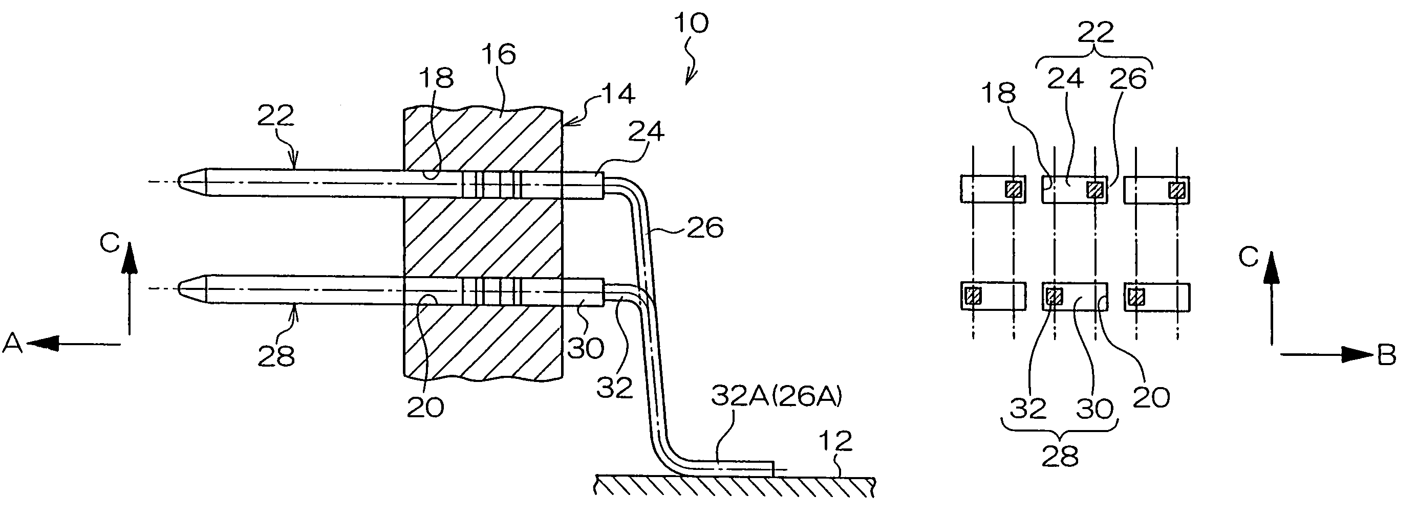
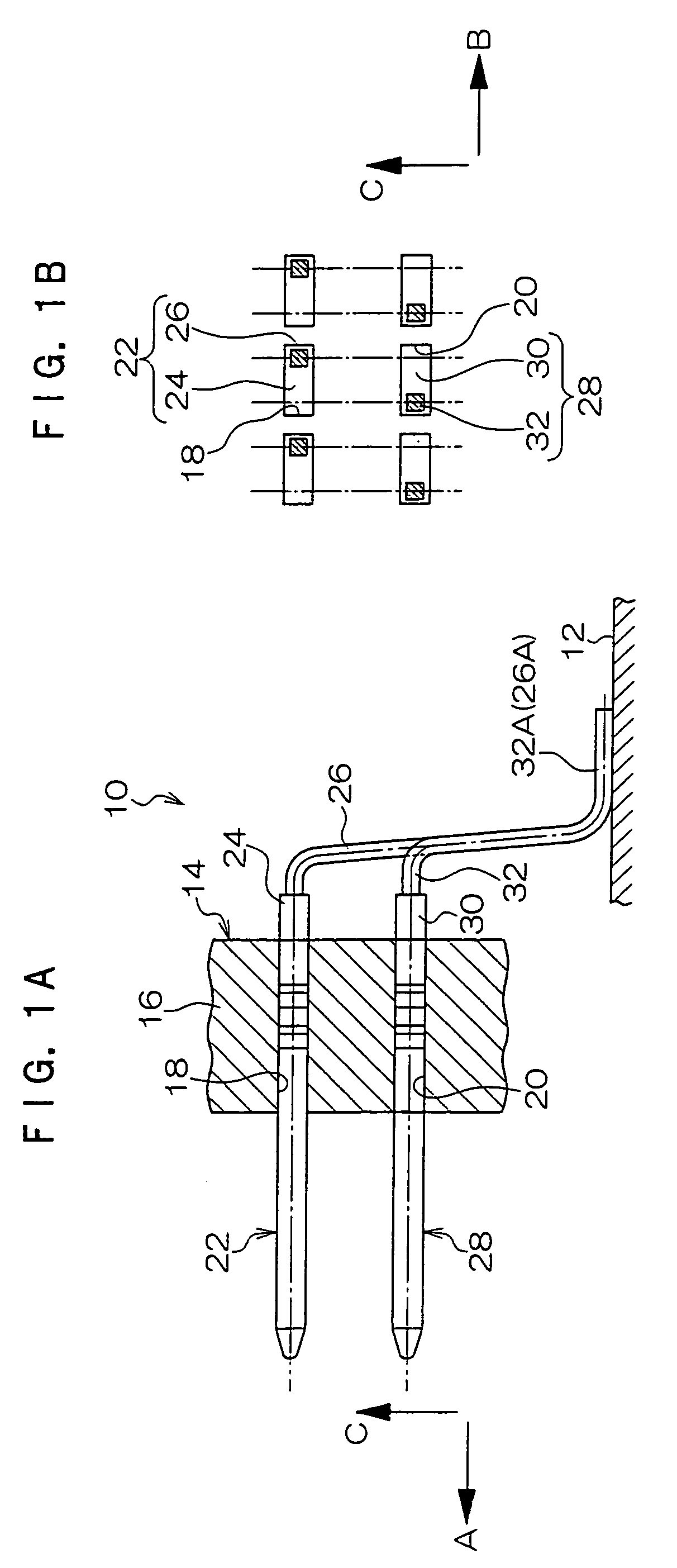
[0030]An upper-level terminal 22 as a first terminal and a lower-level terminal 28 as a second terminal will be described below with reference to FIGS. 1 to 3. The upper-level terminal 22 and the lower-level terminal 28 are applied to a surface-mount connector (SMT connector) 10 according to an embodiment of the invention. For the sake of convenience, in FIGS. 1A and 1B, the direction indicated by an arrow A is set at a front, the direction indicated by an arrow B orthogonal to the arrow A is set at a right side, and the direction indicated by an arrow C orthogonal to both the arrow A and the arrow B is set at an upper side.

[0031]FIG. 1A is a sectional side view schematically showing the SMT connector 10 and a board (for example, a printed board in which lands are printed by screen printing and the like), where the SMT connector 10 is mounted.

[0032]The SMT connector 10 includes a connector main body 14 as the connector housing. The connector main body 14 is formed, e.g. in the subst...


PUM

PropertyMeasurementUnit
widthaaaaaaaaaa
thicknessaaaaaaaaaa
soldering strengthaaaaaaaaaa

Abstract

In a terminal manufacturing method of the present invention, first a thin plate-like body including a thin plate-like terminal portion and a thin plate-like leg portion is formed with a die. The thin plate-like terminal portion has a shape corresponding to a terminal portion 24 of an upper-level terminal 22 and a terminal portion 30 of a lower-level terminal 28. The thin plate-like leg portion has the shape corresponding to a leg portion 26 of the upper-level terminal 22 and a leg portion 32 of the lower-level terminal 28. Then, the upper-level terminal 22 is formed by bending the thin plate-like leg portion toward one side of a plate-thickness direction. Also, the lower-level terminal 28 is formed by bending the thin plate-like leg portion toward the other side of the plate-thickness direction. Thus, by simply changing the bending direction of the thin plate-like leg portion, either the upper-level terminal 22 or the lower-level terminal 28 can be formed. According to the terminal manufacturing method of the invention, when the terminal includes a first terminal mounted in an upper-level mounting hole of a connector housing and a second terminal mounted in a lower-level mounting hole, these two terminals can share a blank material of the same type in common at the manufacturing stage thereof.

Description

CROSS-REFERENCE TO RELATED APPLICATION[0001]This application claims priority under 35 USC 119 from Japanese Patent Application No. 2004-239990, the disclosure of which is incorporated by reference herein.BACKGROUND OF THE INVENTION[0002]1. Field of the Invention[0003]The present invention relates to a method of manufacturing a terminal, which terminal is applied to a connector housing constituting a connector and soldered to a board while projected from the connector housing when the terminal is attached to the connector housing.[0004]2. Description of the Related Art[0005]For example, a surface-mount connector (hereinafter also referred to as SMT connector) and the like are mounted on the board of an electronic device or an electronic circuit by soldering.[0006]Some of the SMT connectors include a connector housing which is formed in a substantially rectangle box, a lower-level terminal (group of terminals), and an upper-level terminal (group of terminals) attached to a side face o...

Claims


Application Information

Patent Timeline
Patent Type & Authority Patents(United States)
IPC IPC(8): H01R12/00
CPCH01R43/16Y10T29/4922H01R12/716
Inventor SASAKI, HAREHIDEOKAMOTO, REIKIKATO, YOSHIAKI
Owner KK TOKAI RIKA DENKI SEISAKUSHO
Why Eureka
Try Eureka