Machined rotor assembly and method of making same

Inactive Publication Date: 2006-03-14
R E PHELSON COMPANY
View PDF51 Cites 23 Cited by
  • Summary
  • Abstract
  • Description
  • Claims
  • Application Information

AI Technical Summary

Benefits of technology

[0013]In another embodiment of the present invention, a rotor assembly includes a plurality of timing teeth with various configurations that are used for engine speed sensing that are machined into a single piece rotor assembly. Machining the teeth into the rotor assembly results in a reduction of tooling and assembly costs associated with the prior art rotor assemblies and with only minimal machining costs. An advantage of the rotor assembly of the present invention is that the hoop strength of the machined rotor is stronger than prior art rotor assemblies because of the machined in speed sensor ring on the outside diameter of the rotor assembly.
[0014]The present invention also contemplates the use of ceramic magnets, or rare earth magnets mounted within the shell of the rotor assembly. Also, thicker magnets than those used in the prior art may be used in the present invention to provide a tighter air gap and thus, increased performance of the internal combustion engine.
[0015]The present invention also contemplates a method of machining the entire rotor out of a single piece of metal, preferably steel. The beginning piece of metal for the entire rotor constructed in accordance with the present invention is only slightly larger than the beginning piece of metal for a prior art hub thus resulting in only slightly higher material cost and machining time. Machining the rotor assembly re

Problems solved by technology

The beginning piece of metal for the entire rotor constructed in accordance with the present invention is only slightly larger

Method used


Image

  • Machined rotor assembly and method of making same
  • Machined rotor assembly and method of making same
  • Machined rotor assembly and method of making same

Examples


Example

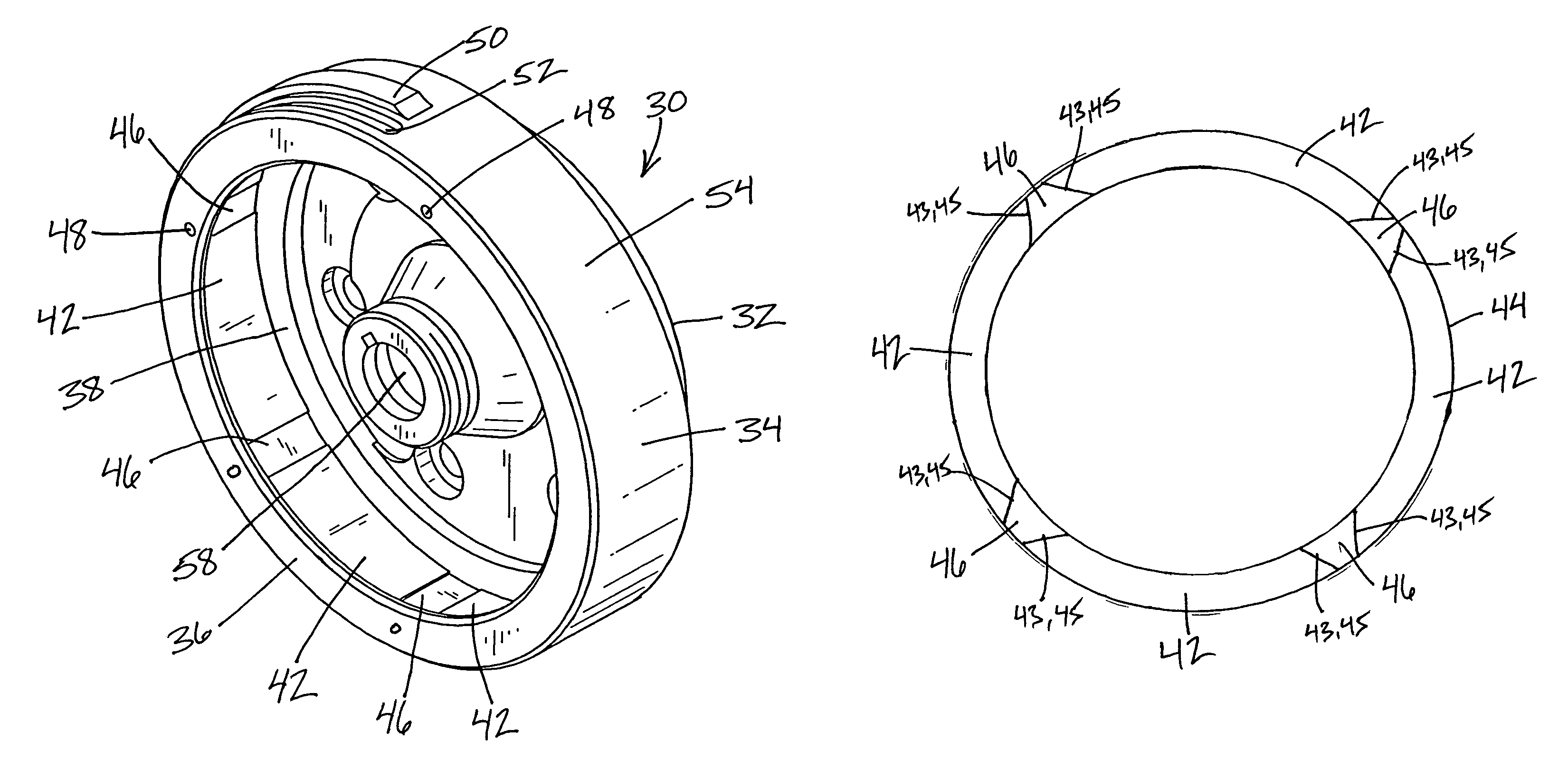
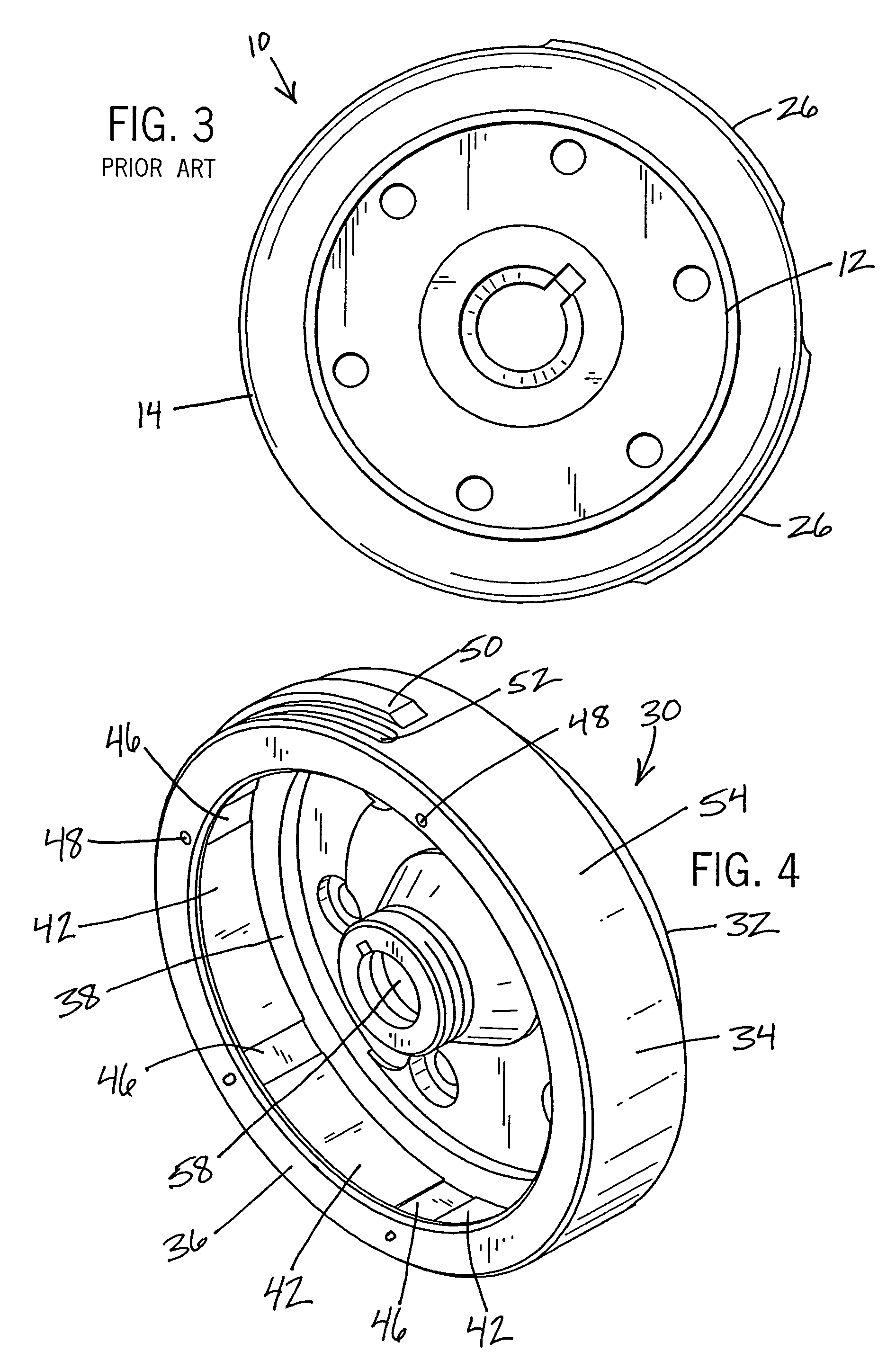
[0036]Referring again to the drawings, FIGS. 4–8 illustrate an embodiment of a rotor assembly 30 constructed in accordance with the present invention. The present invention provides a single piece machined rotor assembly 30 comprising a circular hub 32 and a cylindrical shell 34 extending outwardly from one end of the hub 32, the shell 34 having an upper lip 36 and a lower lip 38 forming a pocket 40 for accepting magnets 42 therein. The hub 32 and shell 34 are machined as a single integral part from a single piece of metal that is roughly the same size used to create the hub of a prior art rotor assembly. The hub 32 preferably includes an opening 58 extending through the center thereof for mounting the rotor assembly 30 on the shaft of an internal combustion engine. The opening 58 is preferably keyed to ensure for proper mounting on the shaft of the internal combustion engine. The upper and lower lips 36, 38 help to hold the magnets 42 in place against the inner sidewall 44 of the s...


PUM


Abstract

The present invention provides a single piece machined rotor comprising a shell having an upper lip and a lower lip, with a pocket formed between the upper lip and the lower lip for mounting magnets therein. The magnets are fixed in place within the inner sidewall of the rotor with an adhesive and spacers. The spacers are positioned between the magnets and are held in place on the shell of the rotor by fasteners. The spacers may be of any type of non-magnetic material that can absorb the heat of the engine. The rotor also preferably includes triggering protrusions and balancing cutouts machined into the shell of the rotor. The cutouts or grooves may be machined into the inner sidewall or the outer sidewall of the rotor. A plurality of timing teeth used for engine speed sensing maybe machined into the single piece rotor assembly. The present invention also contemplates a method of machining the entire rotor out of a single piece of material.

Description

CROSS-REFERENCE TO RELATED APPLICATIONS[0001]This application claims the benefit of U.S. Provisional Application No. 60 / 370,402, filed Apr. 4, 2002, the disclosure of which is incorporated herein by reference.BACKGROUND OF THE INVENTION[0002]The present invention relates generally to a rotor assembly for an internal combustion engine, and more particularly to a single piece machined rotor or flywheel assembly with a plurality of magnets and spacers mounted thereto and a method of reducing the labor and cost of manufacturing a rotor for various types of engines using a permanent magnet ignition and / or charging system.[0003]The present invention relates generally to an electrical system for an internal combustion engine, and more particularly to a charging system for a small internal combustion engine.[0004]The electrical system of a small internal combustion engine typically comprises an ignition system and a charging system. The electrical system can be designed to produce either al...

Claims


Application Information

Patent Timeline
IPC IPC(8): H02K1/28
CPCH02K1/2786F02P1/02F02P7/067H02K21/222H02K11/0015H02K15/165H02K11/21H02K1/2791
Inventor WALKER, JAMES M.
Owner R E PHELSON COMPANY
Why Eureka
Try Eureka