
Veneer underlayment

a technology of underlayment and veining, which is applied in the direction of flooring, covering/lining, construction, etc., can solve the problems of inconvenient force-conductive bonding of rigid materials such as ceramic or porcelain tile and stone, and the sand strata method of tile installation is, for all practical purposes, extinct, and dir

Active Publication Date: 2015-02-10
SCHLUTER SYST LP
View PDF56 Cites 46 Cited by
  • Summary
  • Abstract
  • Description
  • Claims
  • Application Information

AI Technical Summary

Benefits of technology

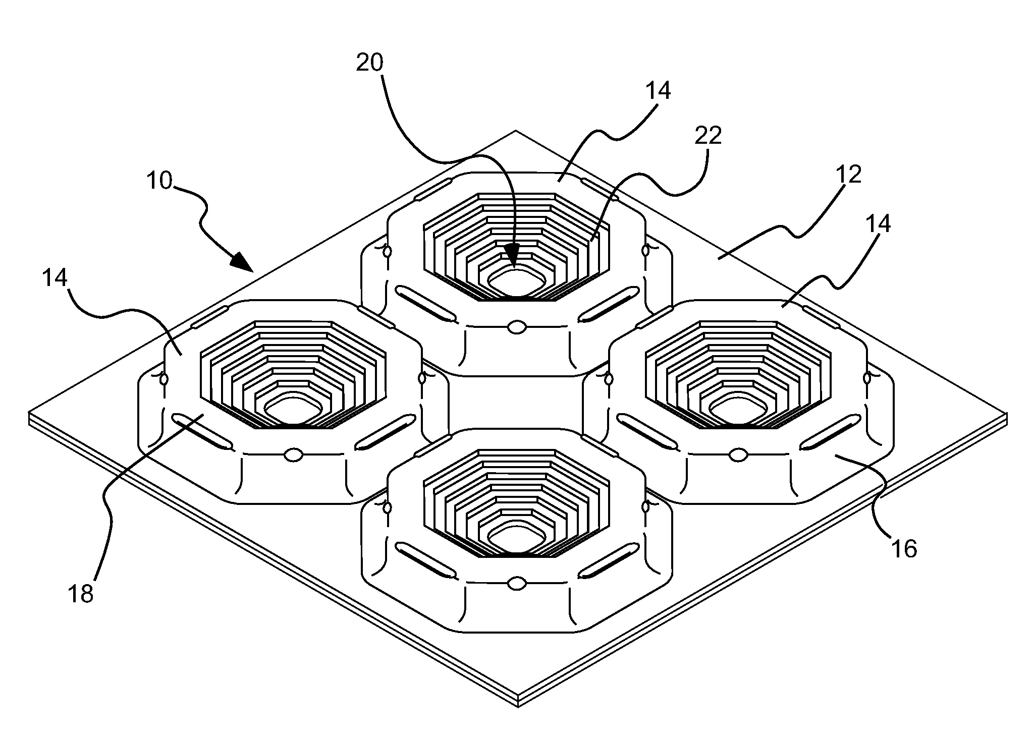
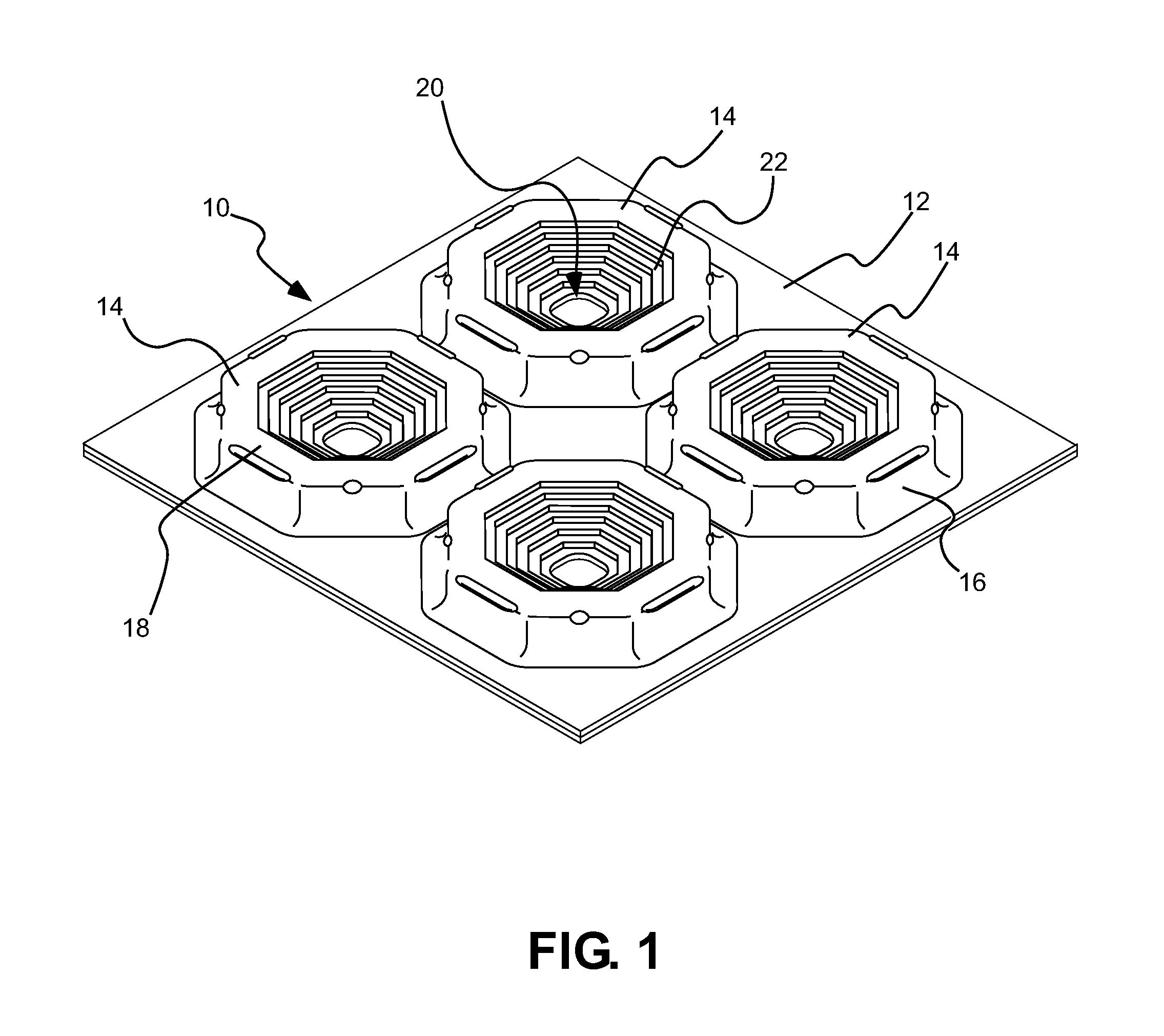
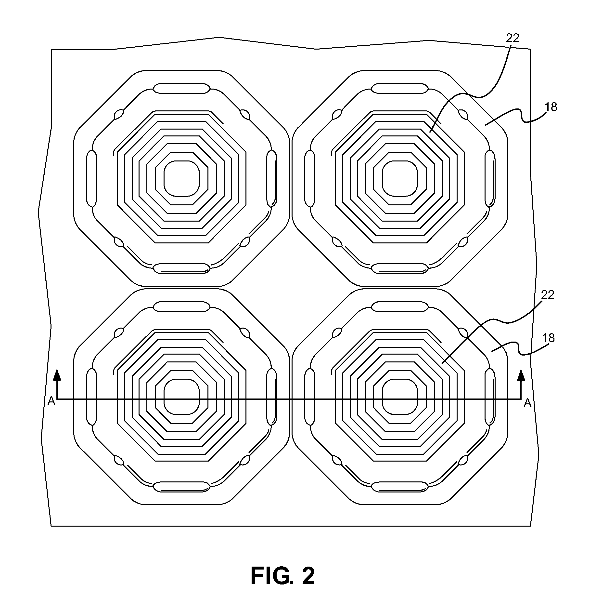
The invention provides an underlayment for use between a veneer material and a foundation surface. The underlayment includes a base layer and a series of supports that create voids in a layer of bonding material used to adhere the veneer material to the underlayment. The supports have an outer wall, a bowl area, and an internal wall that defines the bowl area. The invention also provides a veneer installation that includes the underlayment and a veneer material coupled over the underlayment. The technical effects of the invention include improved stability and durability of the veneer material, reduced shrinking and cracking during installation, and reduced labor costs.

Problems solved by technology

However, due to space (height) requirements and other concerns, the sand strata method for tile installation is, for all practical purposes, extinct.
A direct, force-conductive bond of rigid materials such as ceramic or porcelain tile and stone is not suitable, since these surface materials are sensitive to tensile stresses, particularly when also exposed to live and dead loads.

Method used


Image

  • Veneer underlayment
  • Veneer underlayment
  • Veneer underlayment

Examples


Embodiment Construction

[0015]Before the present invention is disclosed and described, it is to be understood that this invention is not limited to the particular structures, process steps, or materials disclosed herein, but is extended to equivalents thereof as would be recognized by those of ordinarily skilled in the relevant arts. It should also be understood that terminology employed herein is used for the purpose of describing particular embodiments only and is not intended to be limiting.

[0016]It must be noted that, as used in this specification and the appended claims, the singular forms “a” and “the” include plural referents, unless the context clearly dictates otherwise. Thus, for example, reference to a “support” can include one or more of such “supports.”

DEFINITIONS

[0017]In describing and claiming the present invention, the following terminology will be used in accordance with the definitions set forth below.

[0018]As used herein, the term “veneer” is to be understood to refer broadly to a variet...


PUM


Abstract

An underlayment for use between a veneer material and a foundation surface comprises a base layer and a series of supports extending upwardly from the base layer. The supports are configured to create voids in a layer of bonding material used to adhere the veneer material to the underlayment. Each of the supports includes at least one outer wall extending upwardly from the base layer and terminating at an upper lip, a bowl area defined adjacent a center of the support; and an internal wall extending downwardly from the upper lip toward the center of the support to at least partially define the bowl area within each of the supports.

Description

FIELD OF THE INVENTION[0001]The present invention relates generally planar support structures for use in veneer applications. While not so limited, the present invention is well suited for use in tiling and stone applications on floors, ceilings and walls.BACKGROUND OF THE INVENTION[0002]Centuries ago, European builders developed a reliable method of installing tile for high-traffic, high-use applications which relied upon a layer of “sand strata” between a structural substrate and a mortar-bed / tile composite top layer. Modern theory explains that the sand strata “uncouples” the tile from the structure, allowing structural movement without damage to the tile layer. However, due to space (height) requirements and other concerns, the sand strata method for tile installation is, for all practical purposes, extinct.[0003]Approximately twenty-five years ago, a modern analog of the sand strata system was developed in which a thin, polyethylene sheet membrane functions as the uncoupling la...

Claims


Application Information

Patent Timeline
Patent Type & Authority Patents(United States)
IPC IPC(8): E04F13/08E04F15/022E04F15/18
CPCE04F15/022E04F15/185E04F15/182E04F15/02194E04F15/082E04F13/0885
Inventor SCHLUTER, WERNERWEIGE, STEFAN
Owner SCHLUTER SYST LP
Learn More