Noise alarm timer function for three-axis low frequency transponder

a low frequency transponder and noise alarm technology, applied in the direction of anti-theft devices, instruments, program control, etc., can solve the problems of power saving impact, and achieve the effect of reducing power consumption, reducing false wake-up, and reducing battery li

Active Publication Date: 2007-04-24
MICROCHIP TECH INC
View PDF7 Cites 15 Cited by
  • Summary
  • Abstract
  • Description
  • Claims
  • Application Information

AI Technical Summary

Benefits of technology

[0020]A technical advantage of the present invention is substantially eliminating false wake-up from unwanted noise that unnecessarily uses power and thus reduces battery life. Another technical advantage is using a noise alarm function to reduce power consumption and maintain communications. Other technical advantages should be apparent to one of ordinary skill in the art in view of what has been disclosed herein.
is substantially eliminating false wake-up from unwanted noise that unnecessarily uses power and thus reduces battery life. Another technical advantage is using a noise alarm function to reduce power consumption and maintain communications. Other technical advantages should be apparent to one of ordinary skill in the art in view of what has been disclosed herein.

Problems solved by technology

However, if the signal is not valid within the timeout period, e.g., signal does not meet data filter requirements (the data filter may be a digital discrimination filter which may obtain timing information from the internal oscillator), the noise alarm timer will alarm and thereby issue an ALERT output to the external control device.
However, if the signal is found to be invalid, e.g., due to noise for 32 milliseconds duration (not passing the digital discrimination filter), the noise alert signal is sent to the external control device via the ALERT output, causing the external control device to wake up and to take appropriate action which may be determined by a firmware program of the external control device.
Thus, power savings may be affected by reducing the sensitivity of the AFE so that it may not awake in the presence of the noise.

Method used


Image

  • Noise alarm timer function for three-axis low frequency transponder
  • Noise alarm timer function for three-axis low frequency transponder
  • Noise alarm timer function for three-axis low frequency transponder

Examples


Embodiment Construction

[0039]Referring now to the drawings, the details of exemplary embodiments of the present invention are schematically illustrated. Like elements in the drawing will be represented by like numbers, and similar elements will be represented by like numbers with a different lower case letter suffix

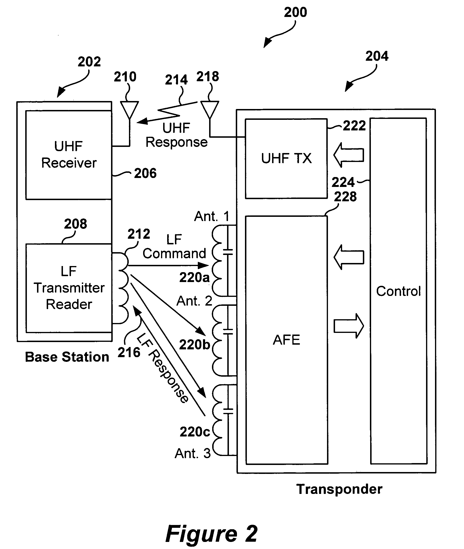
[0040]Referring to FIG. 2, depicted is a schematic block diagram of an exemplary embodiment of a remote keyless entry (RKE) system, according to the present invention. The RKE system, generally represented by the numeral 200, comprises a base station 202, which is normally placed in the vehicle in automobile applications, or in the home or office in security entrance applications, and one or more RKE transponders 204, e.g., key-fobs, that communicate with the base station 202. The base station 202 may comprise a radio frequency receiver 206, antenna 210, and a low frequency transmitter / reader 208 and associated antenna 212. The transponder 204 may comprise a radio frequency transmitter 222, ant...


PUM


Abstract

A remote keyless entry (RKE) transponder has a noise alarm timer having a time interval used for determining whether a received signal meets a predefined condition within a time interval. If the received signal meets the predefined condition within the time interval, the noise alarm timer is disabled and the RKE transponder circuits are enabled so that normal operation in processing the desired signal commences. If the received signal does not meet the predefined condition within the time interval the noise alarm timer issues an alert signal, whereby appropriate action may be taken such as adjusting the channel input sensitivity, disabling a channel, or placing the RKE transponder into a sleep mode in order to reduce the power consumption caused by undesired input signals. A smart wake-up filter determines whether or not the input signal meets the predefined condition within the time interval.

Description

RELATED PATENT APPLICATION[0001]This application claims priority to commonly owned U.S. Provisional Patent Application Ser. No. 60 / 564,830; filed Apr. 23, 2004; entitled “Noise Alarm Timer Function for 3-Axis LF Transponder,” by James B. Nolan, Thomas Youbok Lee, Steve Vernier and Alan Lamphier, which is hereby incorporated by reference herein for all purposes.[0002]This application is related to commonly owned U.S. patent application Ser. No. 11 / 079,765; filed Mar. 14, 2005; entitled “Reducing False Wake-Up in a Low Frequency Transponder,” by James B. Nolan, Thomas Youbok Lee, Alan Lamphier, Ruan Lourens and Steve Vernier; U.S. patent application Ser. No. 11 / 079,878; filed Mar. 14, 2005; entitled “Programmable Wake-Up Filter for Radio Frequency Transponder,” by Thomas Youbok Lee, James B. Nolan, Steve Vernier, Randy Yach and Alan Lamphier; and U.S. patent application Ser. No. 11 / 079,719; filed Mar. 14, 2005; entitled “Dynamic Configuration of a Radio Frequency Transponder,” by Thom...

Claims


Application Information

Patent Timeline
Patent Type & Authority Patents(United States)
IPC IPC(8): B60R25/10H04Q5/22B60R25/00G07C9/00G08C19/00
CPCB60R25/24B60R25/406G07C9/00309G07C2009/00769E05B49/00G07C9/00G08C19/00H04B1/59
Inventor NOLAN, JAMES B.LEE, THOMAS YOUBOKVERNIER, STEVELAMPHIER, ALAN
Owner MICROCHIP TECH INC
Why Eureka
Try Eureka