Drawworks apparatus

a technology of drawing apparatus and drawing rod, which is applied in the direction of drilling pipes, drilling casings, hoisting equipment, etc., can solve the problems of large excess of the life expectancy of the rest of the rig, affecting the design of conventional drawworks, and being either impossible or impractical, so as to reduce the complexity of conventional drawworks design without sacrificing performance, versatility or durability, and the effect of reducing design complexity

Active Publication Date: 2007-05-01
E INK CORPORATION
View PDF9 Cites 34 Cited by
  • Summary
  • Abstract
  • Description
  • Claims
  • Application Information

AI Technical Summary

Benefits of technology

[0015]It is one aspect of the invention to provide a drawworks apparatus that reduces the complexity in conventional drawworks design without sacrificing performance, versatility or durability. The reduction of design complexity is accomplished by eliminating parts, which is made possible by a novel arrangement of drawworks components.
[0016]It is another aspect of the invention to provide a drawworks apparatus in which those components that have been traditionally shown of frequent servicing more accessible by locating them outside of the drawworks frame. For instance, the drawworks apparatus in accordance with the invention provides a novel location for connecting the wire line spool to the drawworks frame via a set of bearings, thereby making it possible to locate the brakes externally, i.e., outside the drawworks frame and the working or operating area of the drawworks wherein the raising and lowering of equipment occurs. Two resulting benefits of arranging the brakes outside the drawworks frame are cooler running brakes and easier maintenance of the brakes. The bearings provided to connect the wire line spool to the drawworks frame are selected on the basis of size and not according to load capacity. Consequently, the fatigue-life rating greatly exceeds the life expectancy of the rest of the rig. Another advantage of locating the bearings for connecting the wire line spool to the drawworks frame in such a manner is that it removes the wire line pull from the drumshaft of the main drum spool and the sand drum spool, thereby reducing its required size and strength as well as improving its reliability.
[0017]It is still another aspect of the invention to provide a drawworks apparatus that continues to provide braking function even in the event of drumshaft failure. This is a result of positioning the drumshafts relative their respective main drum spool and sand drum spool in a manner in which they are only required to carry chain pull, the weight of relatively light-weight components, and the torsional loads need to rotate the spools. This novel arrangement prevents the loss of braking capacity in the event of a drumshaft failure.

Problems solved by technology

Consequently, the fatigue-life rating greatly exceeds the life expectancy of the rest of the rig.
This is either impossible or impractical for conventional drawworks designs.

Method used


Image

  • Drawworks apparatus
  • Drawworks apparatus
  • Drawworks apparatus

Examples


Embodiment Construction

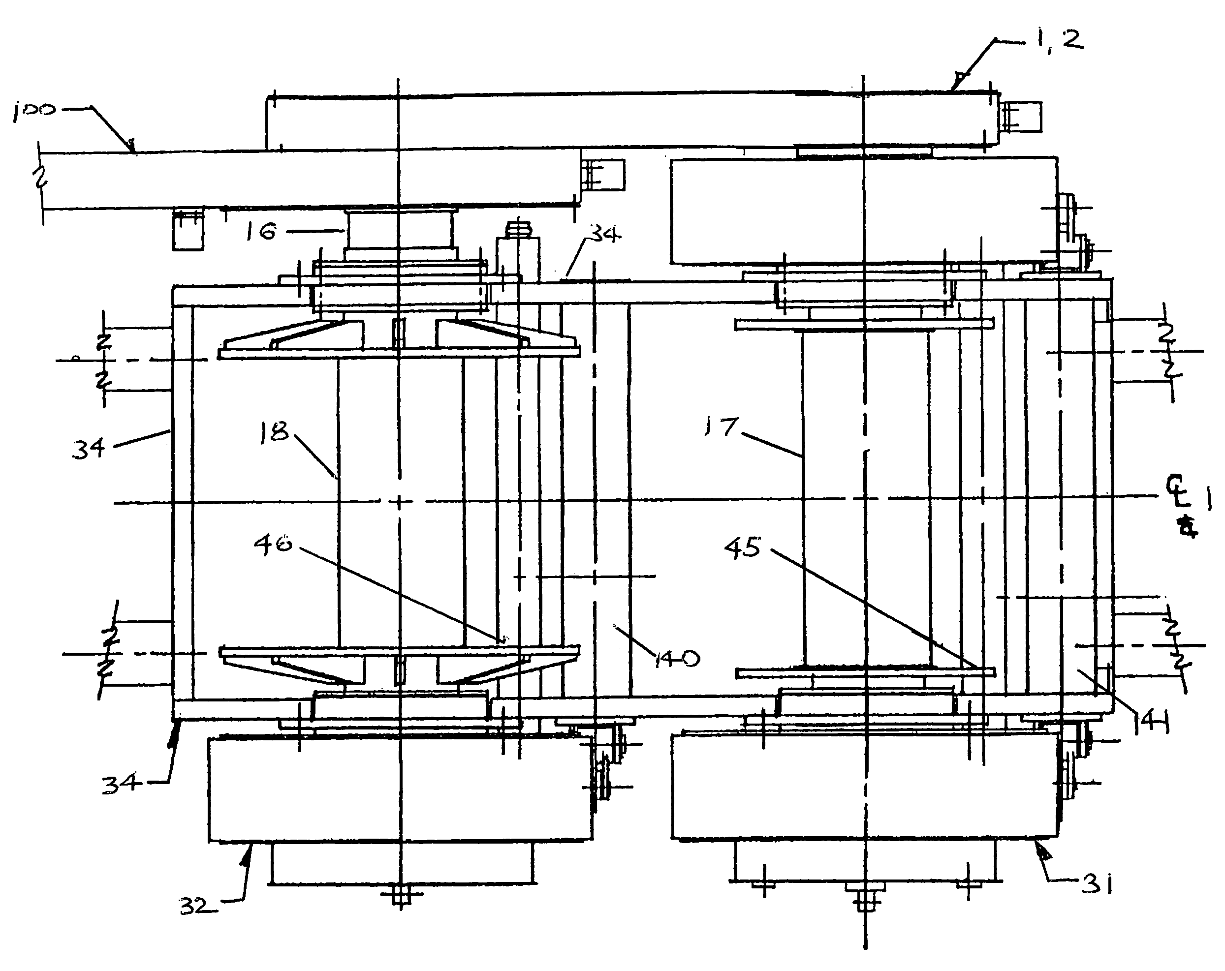
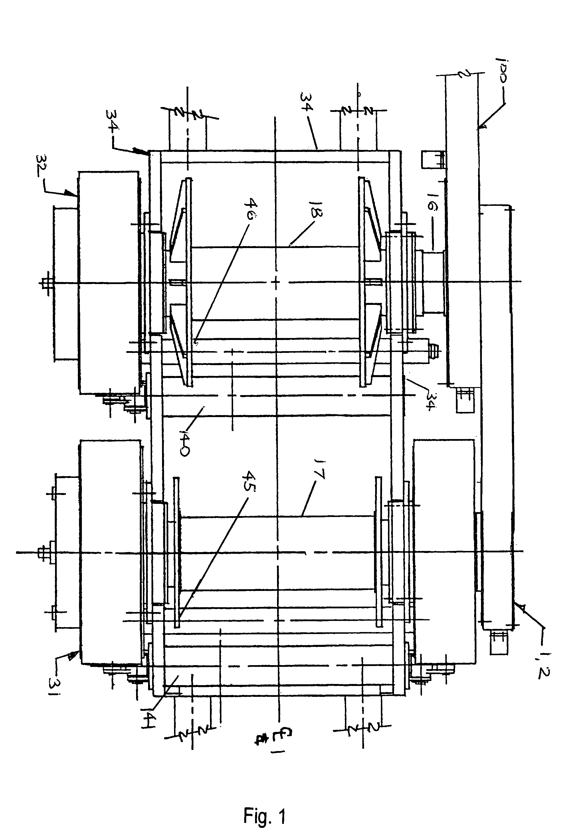
[0034]Referring now to drawing FIGS. 1–5, which show in detail a winch or power transmission apparatus, commonly called a drawworks, including drawworks frame 34, main drum spool 17 and auxiliary or sand drum spool 18 in substantially parallel relation to main drum spool 17. Also provided is a suitable drive device and a brake assembly 31, 32 for main drum spool 17 and sand drum spool 18. By way of suitable bearings 14, main drum spool 17 and sand drum spool 18 are directly attached to the drawworks frame 34. Particularly, main drum spool 17 is supported for rotation on drawworks frame 34 via bearings 14 while sand drum spool 18 is supported for rotation on drawworks frame 34 via bearings 14.

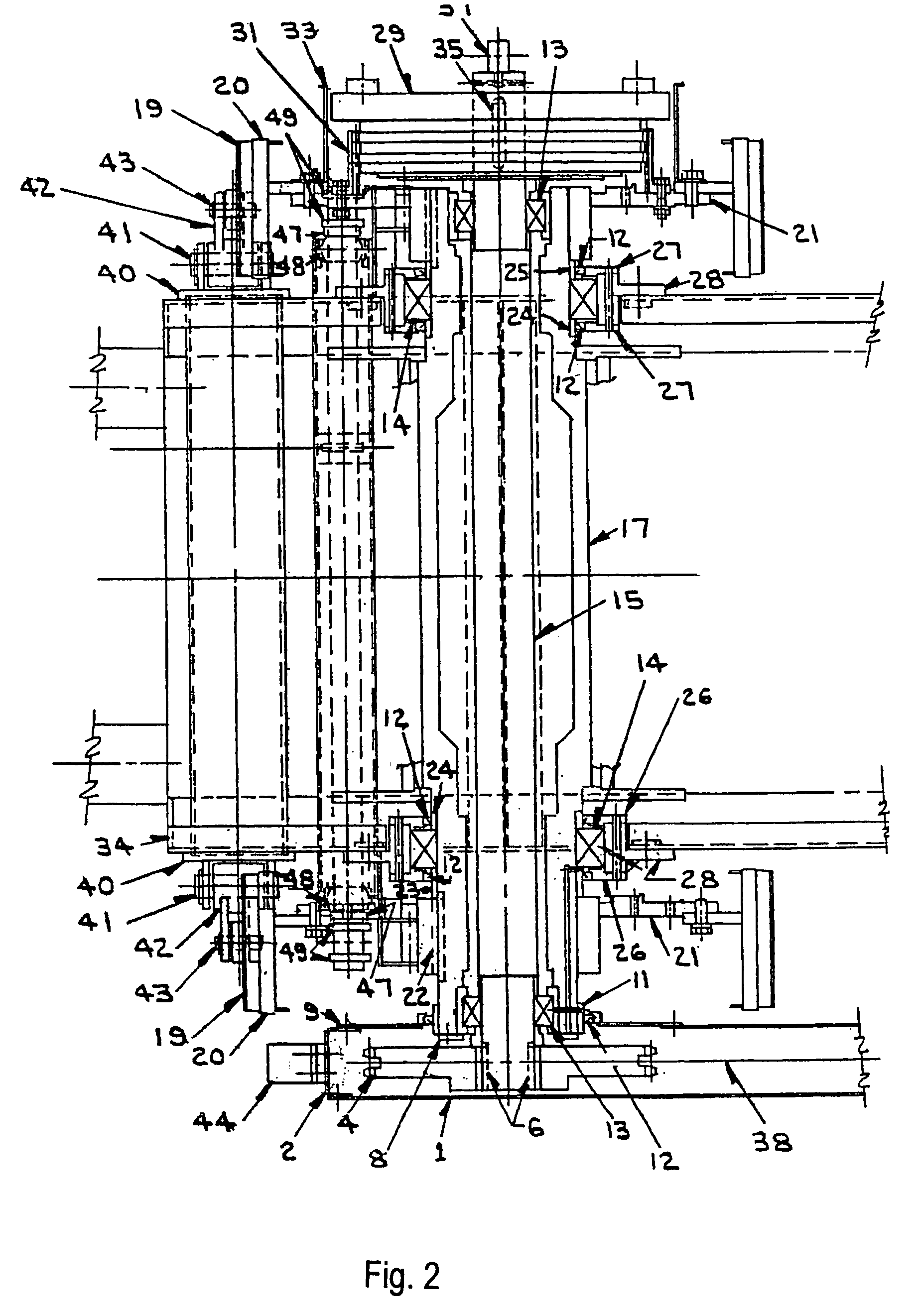
[0035]Central shaft 15 of main drum spool and central shaft shaft 16 of sand drum spool 18 are concentric with their respective drum spool 17, 18 and extend longitudinally outward through respective shaft bores of the spools 17, 18. Shafts 15, 16 are rotatably mounted preferably via anti-frictio...


PUM


Abstract

A drawworks having a main drum spool, a main drum shaft which passes through and is rotatably and concentrically supported by the main drum spool, an auxiliary drum spool, respective drum shafts passing through and rotatably and concentrically supported by the drum spools in a manner in which wireline pull from the spools is isolated therefrom, a clutch mechanism rotatably connected to the shafts and brake mechanisms respectively connected to the main drum spool and the auxiliary drum spool outside the working area of the drawworks.

Description

CROSS-REFERENCE TO RELATED APPLICATIONS[0001]This application claims the benefit of U.S. Provisional Application Ser. No. 60 / 483,469, filed Jun. 30, 2003.BACKGROUND OF THE INVENTION[0002]1. Field of the Invention[0003]The invention relates generally to a drawworks apparatus having a drive mechanism and a brake mechanism that are positioned externally relative to the operating area of the drawworks frame and a shaft which is isolated from wireline pull generated during operation of the drum spool.[0004]2. Description of the Related Art[0005]The drawworks is a type of winch used in the oil well drilling and service industry as a portion of a drilling or servicing rig to raise and / or lower items such as tools and lengths of pipe from a well bore from which oil or other hydrocarbons are produced.[0006]The drawworks typically includes a large-diameter spool that typically supports a length of cable, one or more brakes, a drive system connecting the spool to a power source, and other auxi...

Claims


Application Information

Patent Timeline
Patent Type & Authority Patents(United States)
IPC IPC(8): B66D1/14B66D1/20B66D1/74B66D5/10E21B19/00
CPCB66D1/20B66D1/741B66D5/10E21B19/008
Inventor FRANKS, CHARLES GLLEN
Owner E INK CORPORATION
Why Eureka
Try Eureka