Capacitive mouse

a mouse and capacitive technology, applied in the field of mouse, can solve the problems of direct electrical contact with moving objects, increased friction, wear and corrosion of contacts, and easy mechanical failur

Inactive Publication Date: 2007-05-01
SYNAPTICS INC
View PDF26 Cites 119 Cited by
  • Summary
  • Abstract
  • Description
  • Claims
  • Application Information

AI Technical Summary

Problems solved by technology

Direct electrical contact to moving objects has many well-known disadvantages, such as increased friction, and wear and corrosion of contacts.
First, as moving parts they are susceptible to mechanical failure and may need periodic cleaning.
Second, they are exposed to dirt, moisture, and other contaminants and environmental effects.
Third, as low-cost mechanical devices they may be less sensitive to fine movements than fully electronic devices.
Fourth, electromechanical sensors may be more expensive than purely electronic sensors.
And fifth, optical sensors draw a significant amount of power due to their use of light emitting diodes.
The proliferation of such devices shows both that there is a need for a good scrolling device for use with mice, and that none of the technologies tried so far are completely satisfactory.
However, Scholder only considers resistive and thermal touch sensors, which are less sensitive and less able to be mounted within the plastic enclosure of the mouse than capacitive sensors.

Method used


Image

  • Capacitive mouse
  • Capacitive mouse
  • Capacitive mouse

Examples


Embodiment Construction

[0042]The following description of preferred embodiments of the disclosure is not intended to limit the scope of the invention to these preferred embodiments, but rather to enable any person skilled in the art to make and use the invention.

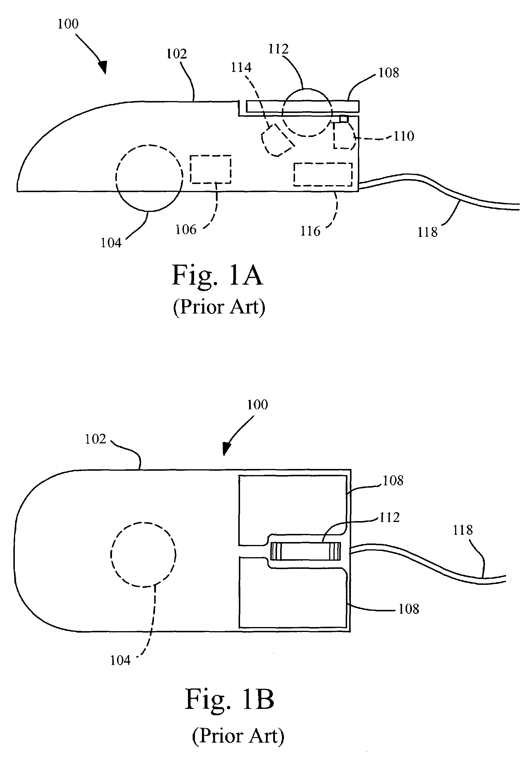
[0043]For reference, FIG. 1A shows the elements of a conventional prior art mouse 100 in side view. Enclosure 102, typically of hard plastic, forms the body of the mouse. Ball 104 protrudes from the bottom of enclosure 102 through a small hole. Motion of the mouse over a flat surface causes ball 104 to rotate; this rotation is measured by rotary encoders 106. Typically two rotary encoders are used to measure motion of the mouse in two orthogonal axes. Buttons 108 form part of the top surface of enclosure 102. Finger pressure on buttons 108 is detected by switches 110 mounted below the buttons. Scroll wheel 112 is mounted between buttons 108; its rotation is measured by rotary encoder 114. Inputs from rotary encoders 106 and 114 and switches 110 ar...


PUM


Abstract

A pointing device some or all of whose elements are made from capacitive sensors. Such elements may include a rotary motion detector which includes a rotating member and a plurality of fixed capacitive detecting members; a rolling ball with patterned conductive surface and a plurality of fixed capacitive detecting members; capacitive touch sensors or capacitive switches to serve as mouse buttons; and a scrolling wheel, knob, or touch surface built from capacitive sensors. The pointing device further includes a capacitance measuring circuit and processor to measure variations of capacitance on the various capacitive elements and to determine the movement of and other activations of the mouse.

Description

CROSS-REFERENCE TO RELATED APPLICATIONS[0001]This application is a continuation of U.S. patent application Ser. No. 09 / 971,181, filed Oct. 4, 2001 now abandoned, which is a divisional of U.S. patent application Ser. No. 09 / 705,593, filed Nov. 3, 2000 now U.S. Pat. No. 6,587,093, which claims priority to U.S. Provisional Application Ser. No. 60 / 163,635, filed Nov. 4, 1999.BACKGROUND OF THE INVENTION[0002]This patent discloses a computer mouse implemented partially or wholly using capacitive sensors. Pointing devices are an essential component of modern computers. One common type of pointing device is the mouse. Computer mice have been well known for many years. U.S. Pat. No. 3,541,541 Engelbart discloses an early mouse implementation using either potentiometers or wheels with conductive patterns to measure the motion. The conductive patterns on these wheels are measured by direct electrical contact. Direct electrical contact to moving objects has many well-known disadvantages, such a...

Claims


Application Information

Patent Timeline
Patent Type & Authority Patents(United States)
IPC IPC(8): G09G5/08G06F3/0354
CPCG06F3/0312G06F3/03543G06F3/03547G06F3/0362G06F2203/0339
Inventor SHAW, SCOTT J.DAY, SHAWN P.TRENT, JR., RAYMOND A.GILLESPIE, DAVID W.ERRINGTON, ANDREW M.
Owner SYNAPTICS INC
Why Eureka
Try Eureka