Reflective illumination system

a technology of reflective illumination and illumination system, which is applied in the direction of instruments, lighting and heating apparatus, optical elements, etc., can solve the problems of complex transmission configuration, complex transmission system of watanabe, and lens requiremen

Inactive Publication Date: 2007-05-01
JDS UNIPHASE CORP
View PDF5 Cites 7 Cited by
  • Summary
  • Abstract
  • Description
  • Claims
  • Application Information

AI Technical Summary

Problems solved by technology

Notwithstanding, Watanabe's system, arranged in a transmissive configuration is complex and requires lenses.

Method used


Image

  • Reflective illumination system
  • Reflective illumination system
  • Reflective illumination system

Examples


Embodiment Construction

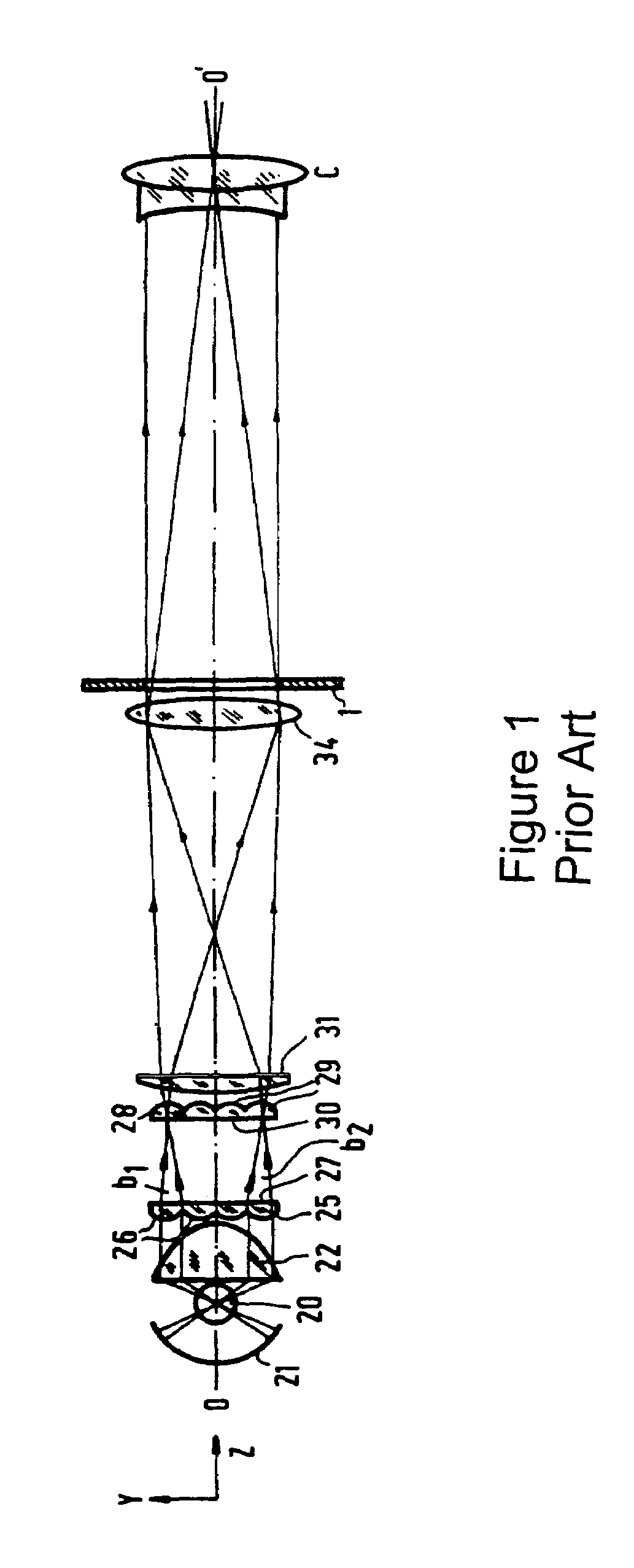
[0030]Referring now to prior art FIG. 1, an illumination system is shown comprising a lamp 20 which emits light in the direction of the display panel 1 as well as in the rearward direction (at the left in FIG. 1). A spherical reflector 21 receiving the rearwardly emitted light and forming an image of this lamp is arranged at the rear side of the lamp. In FIG. 1 the lamp image formed by the reflector 21 coincides with this lamp. It has been assumed that the lamp is transparent to its own light. This will often not be the case in practice. In that case it is ensured that the lamp image is situated beside the lamp. The light emitted by the lamp and its image are received by a condenser lens system 22 which concentrates this light to a parallel beam, in other words it images the lamp to infinity. The parallel beam is incident on a first lens plate 25. The side of this plate facing the source is provided with a matrix of lenses 26 and the other side 27 is preferably flat. Each of these l...


PUM


Abstract

This invention discloses a reflective illumination system for supplying an optical radiation beam along a folded path for illuminating a planar object. The system includes a radiation source, and two facing parabolic dish-shaped arrays of parabolic or dished reflectors. Divergent light received from the light source incident on a first of the arrays is reflected as a larger collimated beam comprising plural separated sub-beams. Each of the reflectors or facets from the first array directs one of the sub-beams to a facet on the second array. The second array reflects the light it receives with a substantially uniform intensity onto a rectangular target location.

Description

CROSS-REFERENCE TO RELATED APPLICATIONS[0001]This application claims priority of U.S. Provisional Patent Application No. 60 / 527,680 filed Dec. 8, 2003 entitled “Reflective Array” which is incorporated herein by reference for all purposes.FIELD OF THE INVENTION[0002]This invention relates to a reflective illumination system for supplying an optical radiation beam along a folded path for illuminating a planar object. The system includes a radiation source, and an array of reflectors. This invention also relates to an image projection apparatus comprising such an illumination system for illuminating at least one image display panel by means of which an image is generated.BACKGROUND OF THE INVENTION[0003]It is a goal of many prior art illumination systems used in projection display to provide a uniform light source having a substantially uniform intensity at and across a planar target location typically normal to the beam direction of the light source. In most instances this target loca...

Claims


Application Information

Patent Timeline
Patent Type & Authority Patents(United States)
IPC IPC(8): G02B27/10G02B17/00F21S2/00G03B21/14F21V13/00G02B17/06G02B17/08G02B27/09
CPCG02B17/0605G02B27/0905G02B27/0977G02B19/0023G02B19/0047G02B19/0033
Inventor PENTICO, CLARKMIN, UNSIGSHI, WEIMIN
Owner JDS UNIPHASE CORP
Why Eureka
Try Eureka