Method for processing image data of optical mouse

a mouse and optical technology, applied in the field of optical mice, can solve the problems of unnatural mouse trajectory, data errors, unnatural mouse trajectory, etc., and achieve the effect of improving the curved trajectory featur

Inactive Publication Date: 2007-05-01
SAMSUNG ELECTRO MECHANICS CO LTD
View PDF8 Cites 6 Cited by
  • Summary
  • Abstract
  • Description
  • Claims
  • Application Information

AI Technical Summary

Benefits of technology

[0010]Accordingly, the present invention has been made keeping in mind the above problems occurring in the prior art, and an object of the present invention is to provide a method for processing image data of an optical mouse, which outputs image signals inputted from an image pixel array of the optical mouse to a personal computer (PC) through a motion vector processing algorithm, thus providing a trajectory curve of the optical mouse with improved curved trajectory features.
[0011]In order to accomplish the above object, the present invention provides a method for processing image data of an optical mouse, which outputs values obtained by filtering, mapping, and piping motion vectors (movement coordinates of the optical mouse; in case of the optical mouse, the movement coordinates thereof are calculated from the variations of voltage values outputted from an image pixel array which reacts according to the amount of light reflected by a surface under the optical mouse to indicate luminance of the surface) with respect to X and Y axes to a PC through an interface, thus minimizing noise components of the optical mouse.

Problems solved by technology

Therefore, if data whose directions vary are temporarily inputted, the motion vectors cannot be effectively adjusted, so the trajectory of the optical mouse is unnaturally represented on a monitor in many cases.
Therefore, in many cases, the trajectory of the mouse becomes unnatural.
Such data errors are generated due to the imprecision of analog processing at a part of the optical mouse which reads data.

Method used


Image

  • Method for processing image data of optical mouse
  • Method for processing image data of optical mouse
  • Method for processing image data of optical mouse

Examples


Embodiment Construction

[0022]Hereinafter, embodiments of the present invention will be described in detail with reference to the attached drawings.

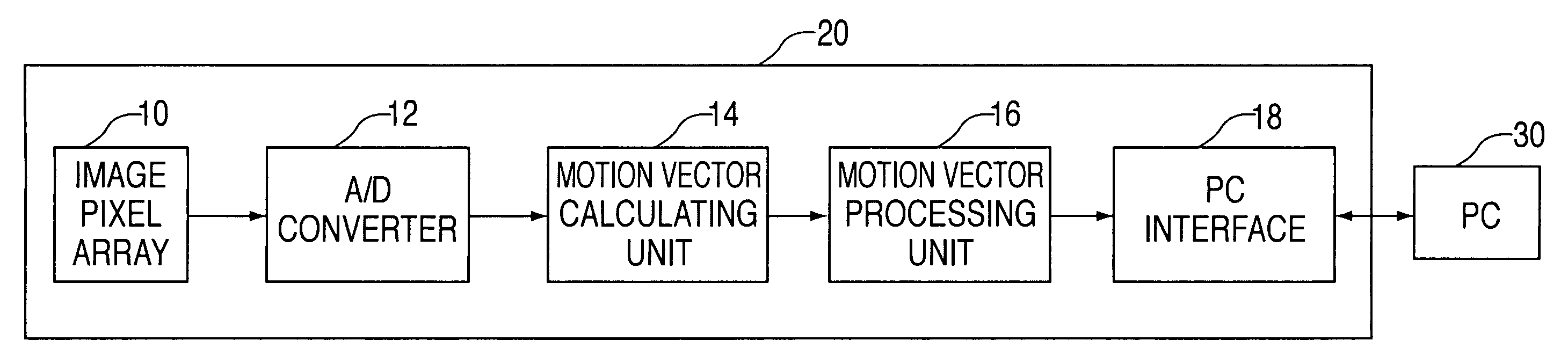
[0023]FIG. 3 is a block diagram of an image processing circuit according to the present invention, and FIG. 4 is a block diagram showing a procedure of processing motion vectors, wherein a procedure performed by a motion vector processing unit 16 of FIG. 3 is divided into three stages and depicted.

[0024]Image data from an image pixel array 10 are outputted at regular intervals (in this case, 588μ sec). Since the image data are analog signals, they are converted into digital signals by an analog / digital converter 12. The converted digital image data are inputted to a motion vector calculating unit 14. The motion vector calculating unit 14 calculates motion vectors using the digital image data. The motion vectors are processed while passing through a filter 40, a mapper 50 and a pipe 60 of the motion vector processing unit 16. Processed results through the motion...


PUM


Abstract

Disclosed herein is a method for processing image data of an optical mouse. In the method for processing image data of an optical mouse, direction and size values of motion vectors which are image data consecutively inputted from an image pixel array are filtered with respect to X and Y axes by a filter. A predetermined number of motion vectors converted by and outputted from the filter are accumulated, and the accumulated values are mapped to conversion values to attenuate noise components and amplify directionality of the motion vectors depending on a speed of the optical mouse by a mapper. The values mapped by the mapper in a plurality of pipes are stored, and a value obtained by adding the plural stored values to each other and dividing the added result value by a conversion factor is transmitted to a personal computer (PC) interface such as a Universal Serial Bus (USB) or PS / 2. Accordingly, the present invention is advantageous in that it minimizes noise components of the optical mouse, and consequently ensures the unnatural movement of a cursor on a PC screen.

Description

BACKGROUND OF THE INVENTION[0001]1. Field of the Invention[0002]The present invention relates generally to optical mice, and more particularly to a method for processing image data of an optical mouse, which obtains an improved trajectory curve of a pointer of the optical mouse.[0003]2. Description of the Prior Art[0004]FIG. 1 is a block diagram of an image processing circuit of a conventional optical mouse.[0005]The optical mouse image processing circuit 5 comprises an image pixel array 1, an analog circuit for controlling the image pixel array 1, an analog / digital converter 2, a motion vector (motion or movement coordinates of the optical mouse) calculating unit 3, and a personal computer (PC) interface 4 for interfacing with a PC 6.[0006]The image-pixel array 1 extracts values, obtained by the reactions of the pixels when the pixels react to light according to the movement of the mouse, from the pixels. In this case, an image pixel array consisting of 18*18 (324) pixels each with...

Claims


Application Information

Patent Timeline
IPC IPC(8): G06K9/40G09G5/08H04B1/66G06F3/0354G06F3/03
CPCG06F3/0317G06F3/038G06F3/0354
Inventor PARK, KEUN-WOOJEONG, JONG-SIKMIN, KYOUNG-JOONGKIM, KANG-JUHWANG, BYOUNG-WONCHOI, WON-TAE
Owner SAMSUNG ELECTRO MECHANICS CO LTD
Why Eureka
Try Eureka