
Cross-spectrum application model for dynamic computing environments in software lifecycle

a technology of dynamic computing and application model, applied in the field of digital processing, can solve the problems of high dissimilarity in nature, problems in relation to manpower, computing power, flexibility, cost and space restrictions of a provider,

Inactive Publication Date: 2007-05-01
SYMANTEC OPERATING CORP
View PDF34 Cites 79 Cited by
  • Summary
  • Abstract
  • Description
  • Claims
  • Application Information

AI Technical Summary

Benefits of technology

"The present invention provides a method for using dynamic computing environments (DCEs) in a software lifecycle. DCEs can be used throughout the phases of the software lifecycle, and each phase's requirements for computing resources can be allocated and configured by a remote user. This allows for remote fulfillment of requirements and reduces the need for on-site resources. The technical effect of this invention is improved efficiency and flexibility in software development."

Problems solved by technology

Also, all these phases may not apply to all three of the software models discussed above and even when they do apply, they may be highly dissimilar in nature.
The different requirements of each phase of the software lifecycle presents problems in relation to manpower, computing power, and flexibility.
With regard to computing power, certain phases may require more powerful machines than other phases, which may cause cost and space restrictions on a provider.
Because of the high cost of workstations, a provider may not be able to purchase an adequate number of workstations or may not be able to justify purchasing a large number of workstations for only one phase of the software lifecycle.
Further, a provider is limited to using the actual machines that are present at the site of the stage of the lifecycle.
Thus, new machines cannot be used during a stage without physically importing them into the site.
Thus, moving from one phase to another results in reconfiguration of computing environments.
The physical reconfiguration results in waste of manpower (i.e., systems administrators) and delays in the lifecycle itself.

Method used


Image

  • Cross-spectrum application model for dynamic computing environments in software lifecycle
  • Cross-spectrum application model for dynamic computing environments in software lifecycle
  • Cross-spectrum application model for dynamic computing environments in software lifecycle

Examples


Embodiment Construction

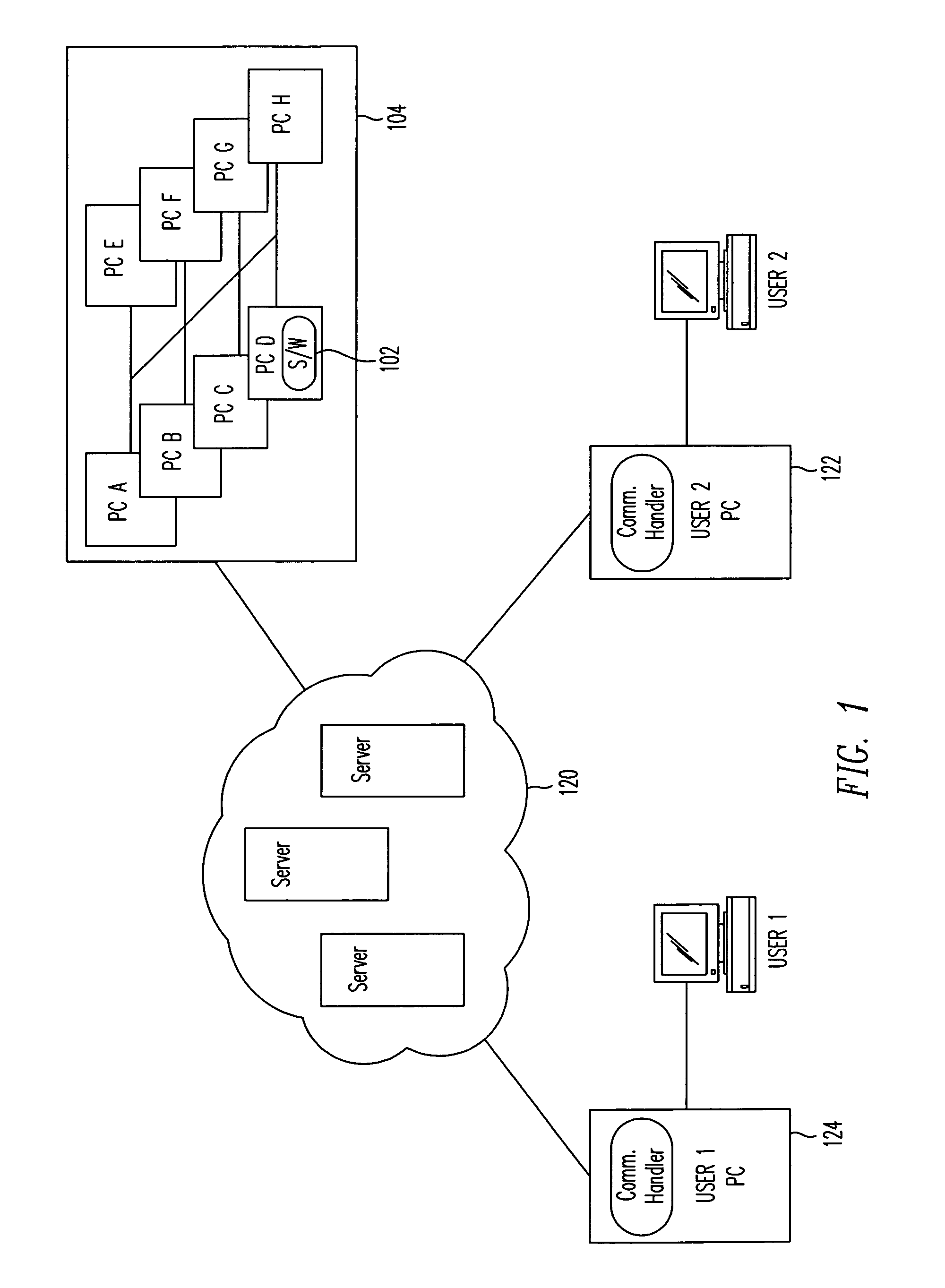
[0023]One embodiment of the present invention allows fast, efficient selection and configuration of processing networks, which can then be accessed and managed remotely. The processing network is referred to as a system including “resources.” A system resource is any hardware, software, or communication components in the system. For example, discrete hardware devices include processing platforms, such as computers or processors, mobile / laptop computers, embedded computing devices, hand-held computers, personal digital assistants, point-of-sale terminals, smart-card devices, storage devices, data transmission and routing hardware etc., without limitation. Additionally, computer peripherals such as monitors, input / output devices, disk drives, manufacturing devices, or any device capable of responding to, handling, transferring or interacting with digital data are also resources. Software, or any other form of instruction, is executed by processors in the system and is also a type of r...


PUM


Abstract

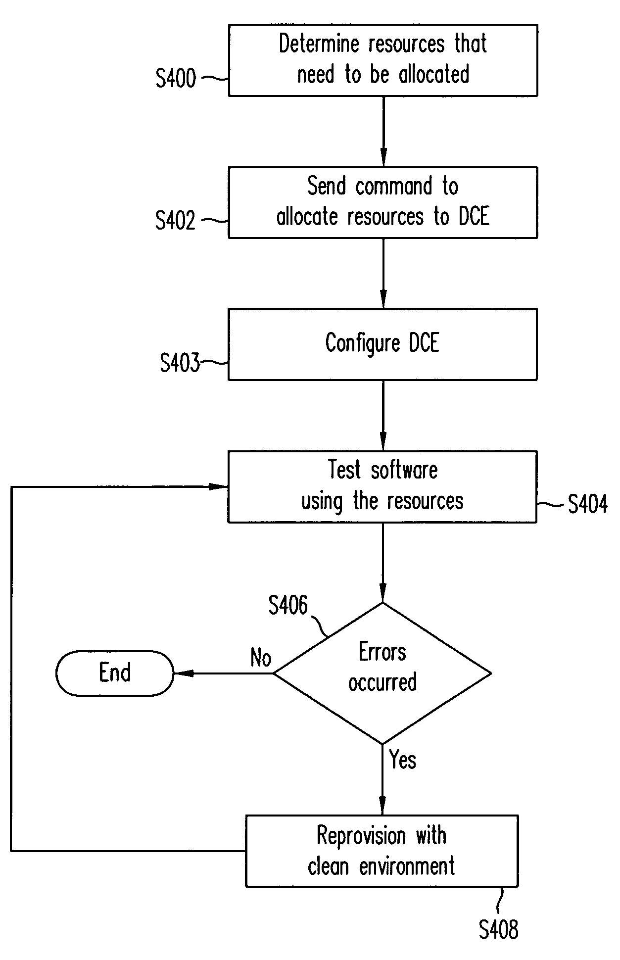
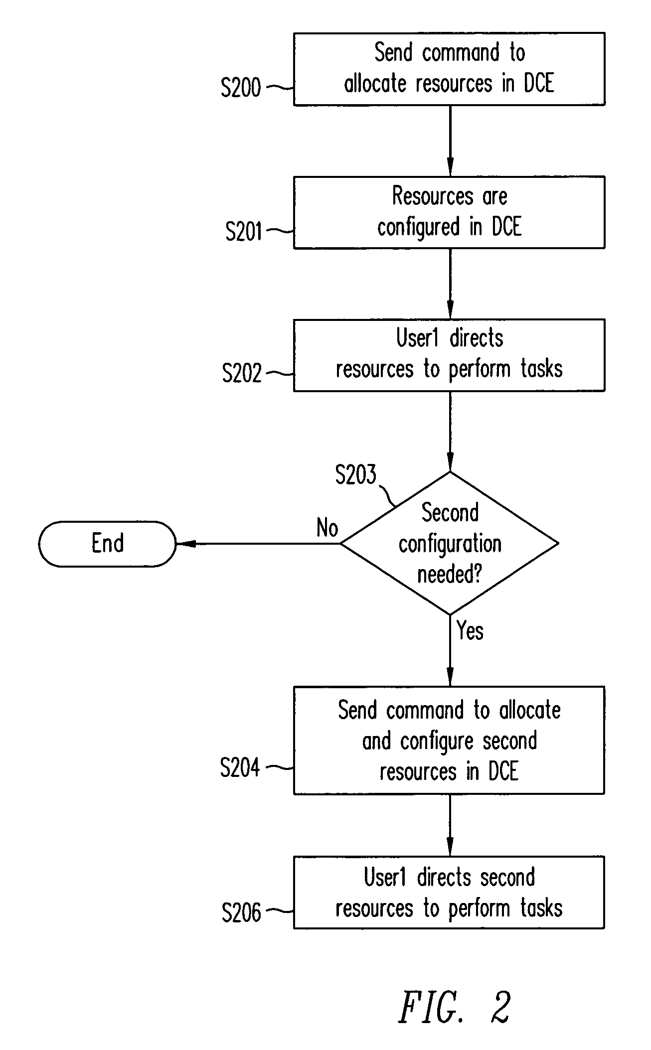
Dynamic Computing Environments (DCEs) are used throughout phases of a software lifecycle. The DCE is configured through a remote user for a phase in the lifecycle. The DCE is then configured according to the command. The user then uses the DCE to fulfill the requirements of the phase. When the phase is completed, a command from the remote user is sent to configure the DCE for another phase. Once the DCE is re-configured, the user uses the DCE to fulfill the requirements of the phase.

Description

CROSS-REFERENCES TO RELATED APPLICATIONS[0001]The present application claims the benefit of priority under 35 U.S.C. § 119 from the provisional patent application, U.S. Provisional Patent Application No. 60 / 261,683, filed on Jan. 11, 2001, which is hereby incorporated by reference as if set forth in full in this document.[0002]This application is related to U.S. Non-Provisional Patent Application entitled “User Interface for Dynamic Computing Environment Using Allocateable Resources” Serial No. 09 / 663,252 filed on Sep. 15, 2000, page no. 1–27, FIGS. 1–5, U.S. Non-Provisional Patent Application entitled “System for Configuration of Dynamic Computing Environments Using a Visual Interface” Ser. No. 09 / 662,990 filed on Sep. 15, 2000, page no. 1–23, FIGS. 1–2, and U.S. Non-Provisional patent application Ser. No. 09 / 861,483 filed on May 17, 2001 entitled “Dynamic Computing Environment Using Remotely Allocable Resources”, which are hereby incorporated by reference, as if set forth in full ...

Claims


Application Information

Patent Timeline
Patent Type & Authority Patents(United States)
IPC IPC(8): G06F9/44
CPCG06F8/20
Inventor BANDHOLE, JAGADISHNANJA, SEKARANBALASUBRAMANIAM, SHAN
Owner SYMANTEC OPERATING CORP
Learn More