Eureka AIR delivers breakthrough ideas for toughest innovation challenges, trusted by R&D personnel around the world.

Display device, position adjustment pattern display program, recording medium, polarized glasses, and method of adjusting position of filter of the display device

Inactive Publication Date: 2007-05-08
SONY CORP
View PDF4 Cites 13 Cited by
  • Summary
  • Abstract
  • Description
  • Claims
  • Application Information

AI Technical Summary

Benefits of technology

[0019]The position adjustment pattern display program can be stored on a desired recording medium, so that, when the program is stored on such a recording medium, it is possible to move the divided wavelength plate filter to adjust its position by reading out the program stored on the recording medium when necessary.
[0021]According to the polarized glasses of the present invention, since the directions of polarization of the polarizing filters, formed at the lenses of both eyes, are the same, the user can view either the polarized light from the image information at the first segment or the polarized light from the image information at the second segment. Therefore, when adjusting the position of the divided wavelength plate filter, only one of the position information patterns is subjected to detection. Consequently, by making an adjustment so that the position information pattern at either segment is only detected, the position of the divided wavelength plate filter can be reliably adjusted.
[0023]By displaying the adjustment pattern on the display device, the position of the filter, which cannot not be easily adjusted in the related technologies, can be easily adjusted, so that the viewer can actually view an optimal image with the filter being positioned at the optimal position. When the method not using glasses is used or in the method for performing a displaying operation on a plurality of screens, an optimal image can be similarly viewed.

Problems solved by technology

Color separation methods, such as the anaglyph method, have many qualitative problems including a difficulty in color presentation and reduction in the field of view.
The method using polarized glasses has problems such as the necessity of generally using two projection devices.
However, this is not easy to achieve, thereby giving rise to the following problems.
The first problem occurs when mounting the divided wavelength plate filter.
In addition, since the pixels of the display surface having higher resolution are becoming more minute, a high-definition panel can be obtained, but it is very difficult to precisely secure a corresponding high-definition divided wavelength plate filter, which is produced in a separate process, in correspondence with the pixels of the predetermined areas.
In addition, various factors, such as heat and vibration during conveyance of the divided wavelength plate filter, often cause the position of the divided wavelength plate filter to be shifted.
Further, due to manufacturing problems, in order to maintain the precision of the predetermined areas, a glass substrate is, in general, often used for the divided wavelength plate filter, so that its position is, in particular, shifted by its own weight.
Still further, various durability conditions, such as deterioration of the fixing agent, may cause the divided wavelength plate filter to be shifted, so that, when the hardened resin is shifted, it is very difficult to correct the position of the divided wavelength plate filter afterwards.
Therefore, the relatively expensive display panel becomes utterly useless.
Therefore, the position where the filter is previously secured is not necessarily the optimal position when an image is being viewed. FIG. 25 shows this situation.
As a result, crosstalk between images occurs, so that proper three-dimensional images cannot be displayed.

Method used


Image

  • Display device, position adjustment pattern display program, recording medium, polarized glasses, and method of adjusting position of filter of the display device
  • Display device, position adjustment pattern display program, recording medium, polarized glasses, and method of adjusting position of filter of the display device
  • Display device, position adjustment pattern display program, recording medium, polarized glasses, and method of adjusting position of filter of the display device

Examples


Embodiment Construction

[0049]Hereunder, a description of embodiments of the present invention will be given with reference to the drawings. In the embodiments, three-dimensional image display devices which display image information including parallax information will be mainly described. By a similar structure, a displaying operation can be performed on from one display screen to a plurality of display screens, so that a display device which performs such a displaying operation can have a similar structure.

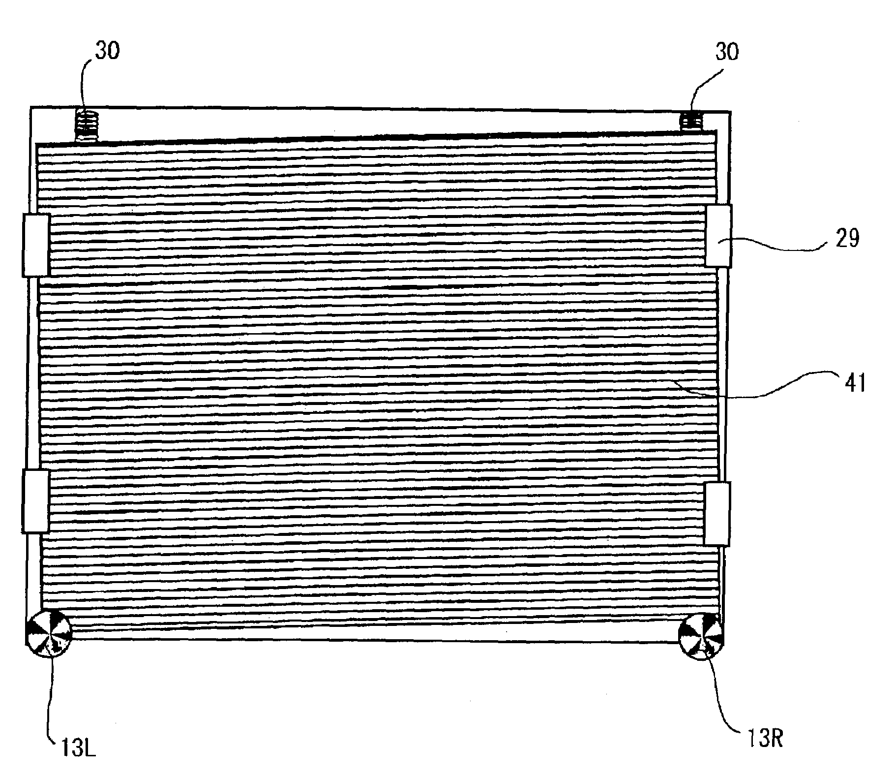
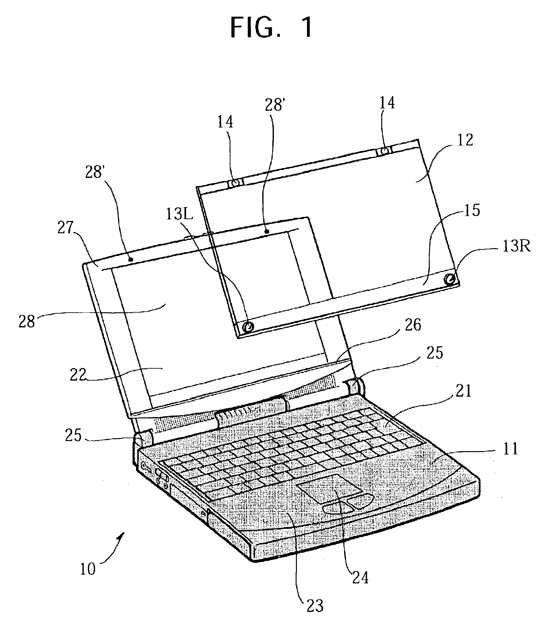
[0050]The general structure of a three-dimensional image display device 10 of an embodiment of the present invention is shown in FIG. 1. The three-dimensional image display device 10 of the embodiment comprises a notebook computer 11, a divided wavelength plate filter 12 mountable to the notebook computer 11, a pair of left and right adjusting screws (a right adjusting knob 13R and a left adjusting knob 13L) serving as position adjusting means integrally mounted to the divided wavelength plate filter 12...


PUM


Abstract

Even if a divided wavelength plate filter is mounted, it is possible to reliably display a three-dimensional image or perform a displaying operation on from one screen to a plurality of screens. In a display device, the relative positions of an image display section and a divided wavelength plate filter for rotating polarized light from image information at a first segment in a direction that is different from the direction of polarized light from image information at a second segment can be adjusted. At the time of positional adjustment, the display device displays a position adjustment pattern (112) having colors, figures, characters, symbols, diagrams, or designs, or combinations thereof which differ from each other depending on the segment.

Description

BACKGROUND OF THE INVENTION[0001]The present invention relates to a display device which allows an image containing parallax information to be viewed three-dimensionally or which can perform a displaying operation on from one screen to a plurality of screens, a position adjustment pattern display program used in such a display device, a recording medium, polarized glasses, and a method of adjusting the position of a filter of the display device. More particularly, the present invention relates to a filter position adjustment pattern for displaying an optimal three-dimensional image or for performing a displaying operation on from one screen to a plurality of screens when a divided wavelength plate filter is mounted, and a method of adjusting the position of the filter.[0002]Hitherto, various attempts have been made to provide technologies for presenting images three-dimensionally. In many fields, such as photography, movies, and television, methods for displaying images three-dimens...

Claims


Application Information

Patent Timeline
IPC IPC(8): G09G5/00G02B30/25G02B27/28G09F9/00G09F9/35G09G3/20G09G3/36H04N13/00H04N13/04
CPCG02B27/26H04N13/0425H04N13/0434H04N13/0452H04N13/0497H04N13/0285H04N13/0409H04N13/0422H04N13/337H04N13/324H04N13/356H04N13/31H04N13/286H04N13/327H04N13/398G02B30/25H04N13/00
Inventor SATOH, SEIJISEKIZAWA, HIDEHIKO
Owner SONY CORP
Why Eureka
Eureka Blog
Learn More