Inspection of transparent substrates for defects

a transparent substrate and inspection technology, applied in spectrum investigation, optics, instruments, etc., can solve the problems of small changes in the intensity profile of beams, reduce interference effects that can complicate interpretation of contrast patterns, and reduce interference effects. , the effect of high spatial coheren

Inactive Publication Date: 2007-05-08
CORNING INC
View PDF35 Cites 9 Cited by
  • Summary
  • Abstract
  • Description
  • Claims
  • Application Information

AI Technical Summary

Benefits of technology

[0006]According to some embodiments of the invention, optical path length variations are observed indirectly by illuminating the glass with a highly spatially coherent beam. Interference effects that can complicate interpretation of the contrast pattern are reduced by use of a temporally incoherent beam, i.e. one with a very short coherence length. According to certain embodiments, if the OPL variations have a period less than or about equal to the beam size, the optical path length variation causes phase distortion in the beam which can be measured, thus providing a physical effect related to the variation of the path length (on a scale of about 10 nm.)
[0007]In certain preferred embodiments, measurement of the phase distortion is accomplished by spatially filtering the light, for example, by using a superluminescent diode (SLD) light source coupled to single-mode fiber. The SLD preferably has a wavelength spectrum wide enough to provide a coherence length shorter than the optical path length through the glass, to reduce interference effects. High spatial coherence can be provided by the use of single-mode fiber. Preferably, the beam is launched from fiber, and a lens placed one focal length away from the fiber end produces a collimated beam. Instead of using an optical fiber, spatial filtering may also be accomplished by transmitting the light through a small opening, preferably less than 50 microns in diameter, and preferably less than about 20 microns.
[0009]The present invention has wider spatial frequency response range resulting in higher resolution of defects on the glass surface than in prior art systems. The invention provides a repeatable measurement that is sensitive to low level defects (e.g., less than about 100 nm, preferably less than about 50 nm and as small as about 1 nm OPL variations). The system and apparatus are compact and can rapidly measure defects.

Problems solved by technology

According to one aspect, phase distortion from defects in the substrate results in small changes in the intensity profile of the beam at the slit position.

Method used


Image

  • Inspection of transparent substrates for defects
  • Inspection of transparent substrates for defects
  • Inspection of transparent substrates for defects

Examples


Embodiment Construction

[0018]Before describing several exemplary embodiments of the invention, it is to be understood that the invention is not limited to the details of construction or method steps set forth in the following description. The invention is capable of other embodiments and of being practiced or carried out in various ways.

[0019]The present invention relates to apparatus, systems and methods for inspecting transparent substrates such as glass sheets. The invention is particularly useful for detecting one dimensional OPL variations on the order of about 100 nm or less, for example, less than about 50 nm or 10 nm, and as small as about 1 nm on liquid crystal display substrates.

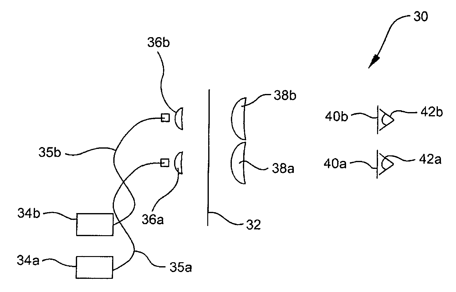
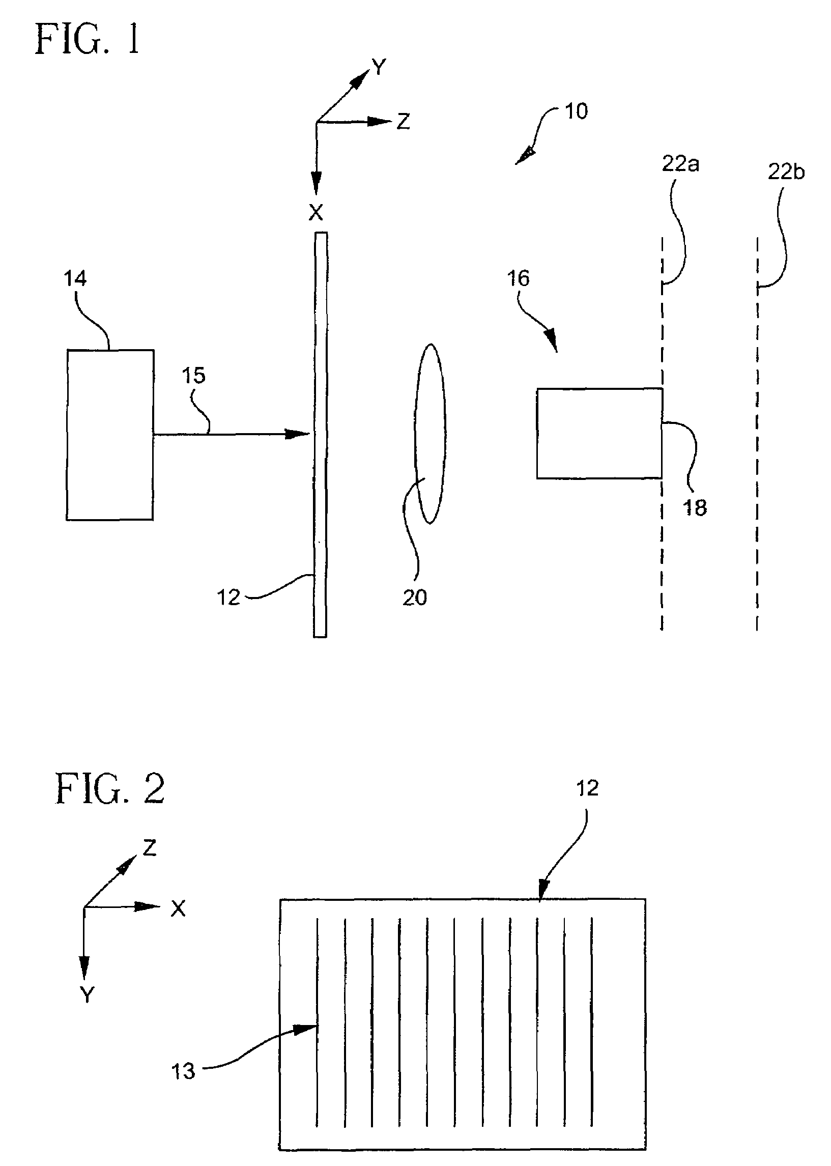
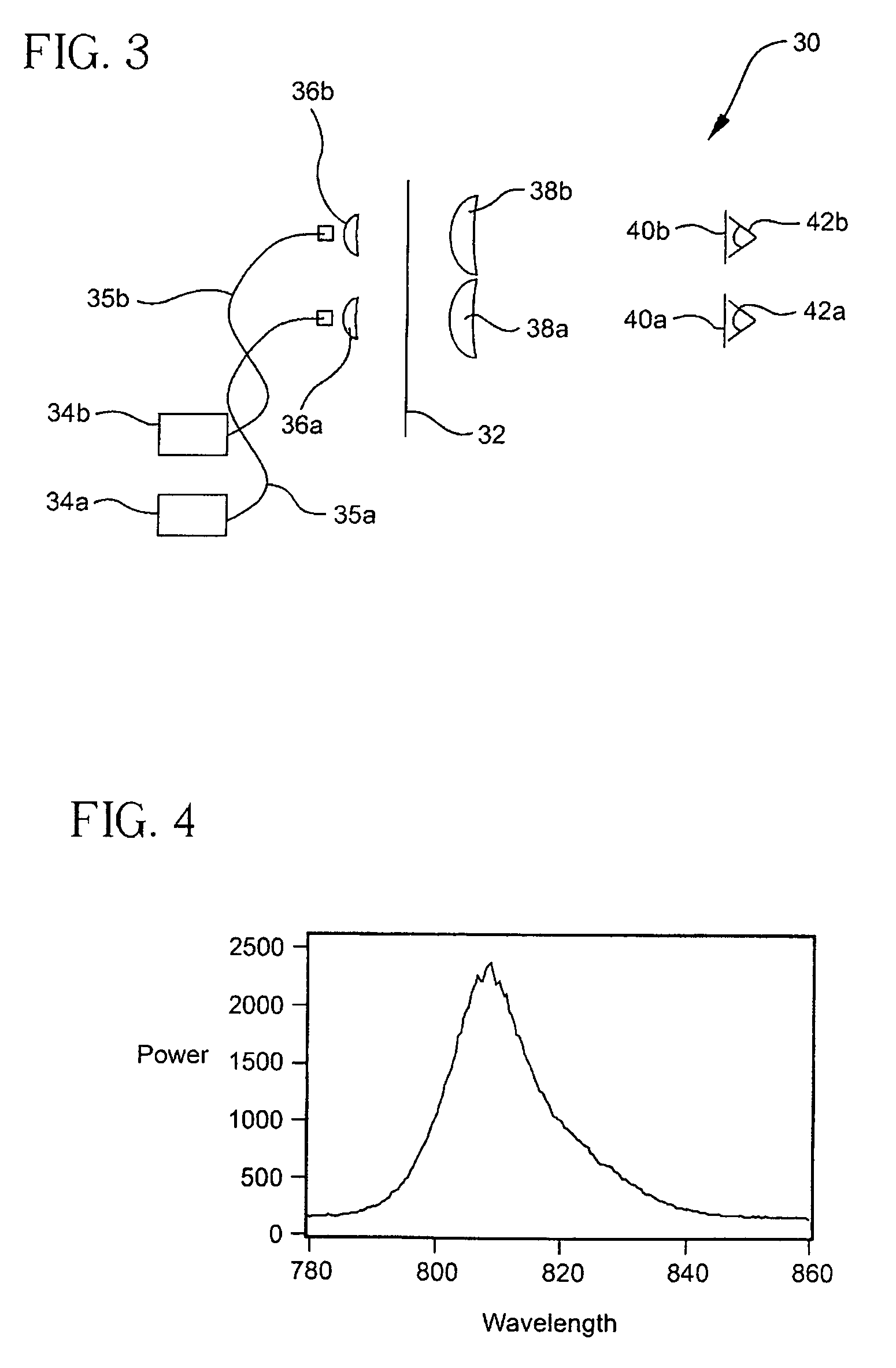
[0020]Referring to FIG. 1 and according to a first embodiment of the invention, an apparatus 10 for measuring defects in or on transparent substrates 12 is provided. The apparatus is particularly useful for measuring cord defects in glass substrates used in liquid crystal displays. As shown in FIGS. 1 and 2, the optical ...


PUM

PropertyMeasurementUnit
path lengthaaaaaaaaaa
diameteraaaaaaaaaa
diameteraaaaaaaaaa

Abstract

Methods, apparatus and systems for the detection of defects in transparent substrates such as glass sheets are disclosed. The methods, apparatus and systems are capable of detecting optical path length variations in transparent substrates smaller than 100 nm.

Description

CROSS-REFERENCE TO RELATED APPLICATION[0001]This application is a continuation of U.S. application Ser. No. 10 / 382,689, filed on Mar. 5, 2003 now U.S. Pat No. 7,142,295 the content of which is relied upon and incorporated herein by reference in its entirety, and the benefit of priority under 35 U.S.C. §120 is hereby claimed.FIELD OF THE INVENTION[0002]This invention relates to systems, methods and apparatus for the inspection of substrates to determine defects. The invention is particularly useful for the measurement of one dimensional optical path length variations in glass sheets.BACKGROUND OF THE INVENTION[0003]Defects in transparent substrates such as glass sheets are typically detected utilizing human inspectors and manual methods. For example, in the detection of defects such as cord and streak in glass substrates used in liquid crystal displays (LCDs), a shadow method is used to detect the defects. According to this method, a sheet of glass (typically about 1 meter wide×2 met...

Claims


Application Information

Patent Timeline
Patent Type & Authority Patents(United States)
IPC IPC(8): G01N21/00G01N21/41G01N21/896G01N21/95
CPCG01N21/41G01N21/958G01N2021/9513G01J3/30G02F1/13
Inventor GAHAGAN, KEVIN T.HILTNER, JASON F.
Owner CORNING INC
Why Eureka
Try Eureka