Method, device and system for generating and receiving a phase polarization modulated signal

a phase polarization modulated and signal technology, applied in the field of communication transmission, can solve the problems of strong non-linear effect, inability to avoid interference effect, inability to bear dqpsk signal in the prior art, etc., and achieve the effect of reducing interference effect of optical signal during transmission, reducing interference effect, and improving spectral efficiency

Inactive Publication Date: 2012-02-02
HUAWEI TECH CO LTD
View PDF6 Cites 6 Cited by
  • Summary
  • Abstract
  • Description
  • Claims
  • Application Information

AI Technical Summary

Benefits of technology

[0013]In view of the above, in the embodiments of the present invention, phase modulation and polarization modulation are combined at a signal transmitting end, so that each pulse, that is, each constellation point of the generated phase polarization modulated signal may carry information of three bytes or four bytes, and spectral efficiency is improved by 1.5 times to 2 times in comparison with the DQPSK signal in the prior art (each pulse thereof carries information with two bytes). Therefore, with such a transmission manner, the optical signal used in the embodiments of the present invention may carry service information at a higher rate, and requirements of the ever-increasing services on a capacity of a transmission network are met. In addition, because the phase polarization modulated signal is polarization modulated, a polarization state of the phase polarization modulated signal only includes X / Y polarization, and two orthogonal polarization states may not be interfered. In this way, interference effect of the optical signal during transmission is reduced through polarization keying modulation. Further, because differential coding is adopted, the noise floor between adjacent pulses is cancelled, thereby significantly improving transmission performance of the optical signal and contributing to the implementation of the products.

Problems solved by technology

Therefore, the DQPSK signal in the prior art cannot bear and transmit information at a higher rate.
In addition, because polarization between adjacent code elements of the DQPSK signal in the prior art is the same, an interference effect cannot be avoided, and the non-linear effect is strong during transmission.

Method used


Image

  • Method, device and system for generating and receiving a phase polarization modulated signal
  • Method, device and system for generating and receiving a phase polarization modulated signal
  • Method, device and system for generating and receiving a phase polarization modulated signal

Examples


embodiment 1

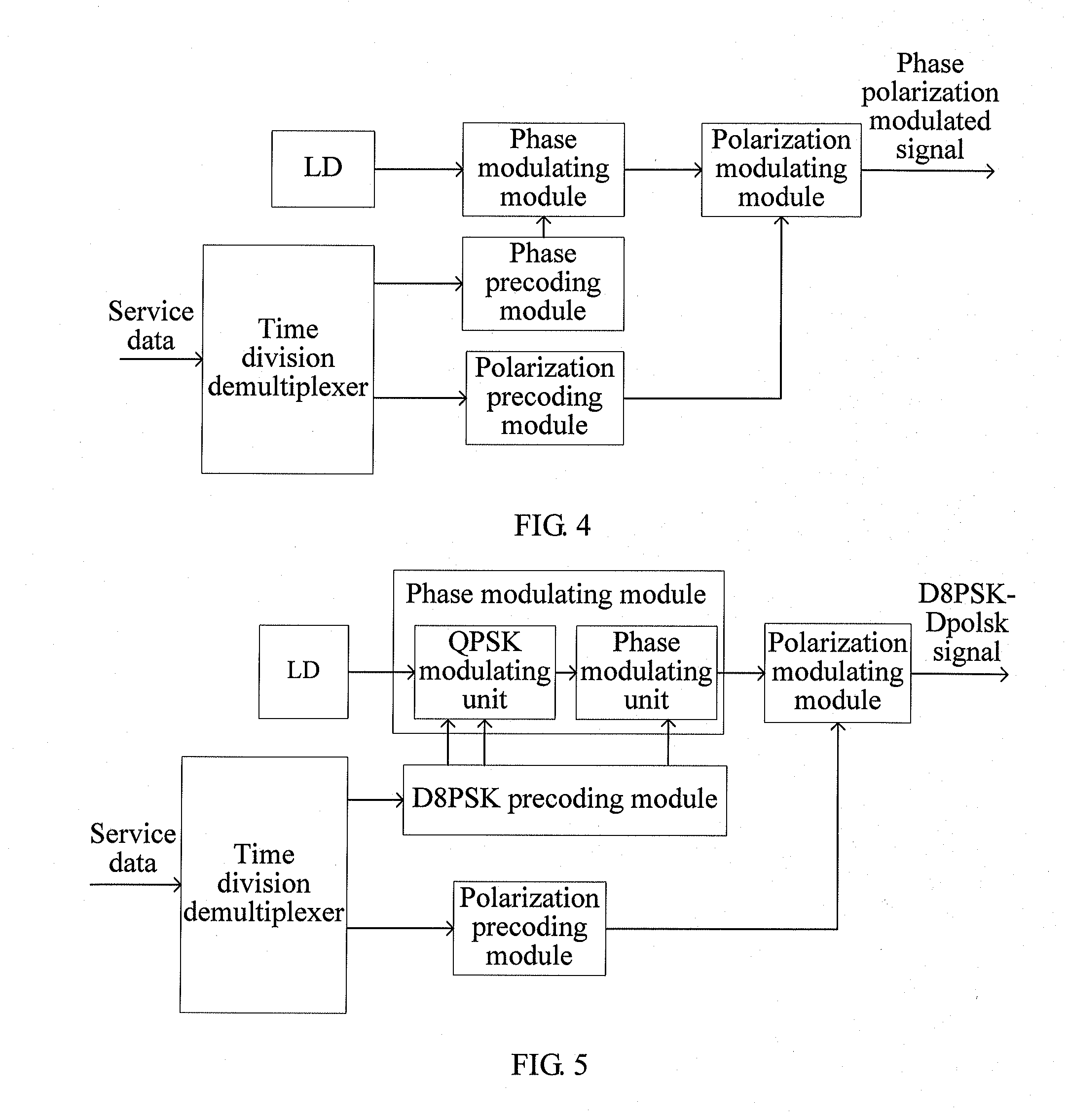
[0025]FIG. 4 is a schematic diagram of a device for generating a phase polarization modulated signal of the present invention, and the device includes the followings. An LD is configured to output an optical signal. A time division demultiplexer is configured to divide service data to be transmitted into first sub-service data and second sub-service data. In order to meet requirements of an optical communication system, the LD is required to output a signal with a stable wavelength. The time division demultiplexer adopted in this embodiment of the present invention performs time division demultiplexing processing on the service data to be transmitted to divide the service data into two paths of service data in an intervening selection manner. A specific manner may be various, such as 1:2 or 1:4. In various implementation situations, power division is performed on the electric signal, and data is selected by selecting switches, so as to obtain two paths of service data. A phase prec...

embodiment 3

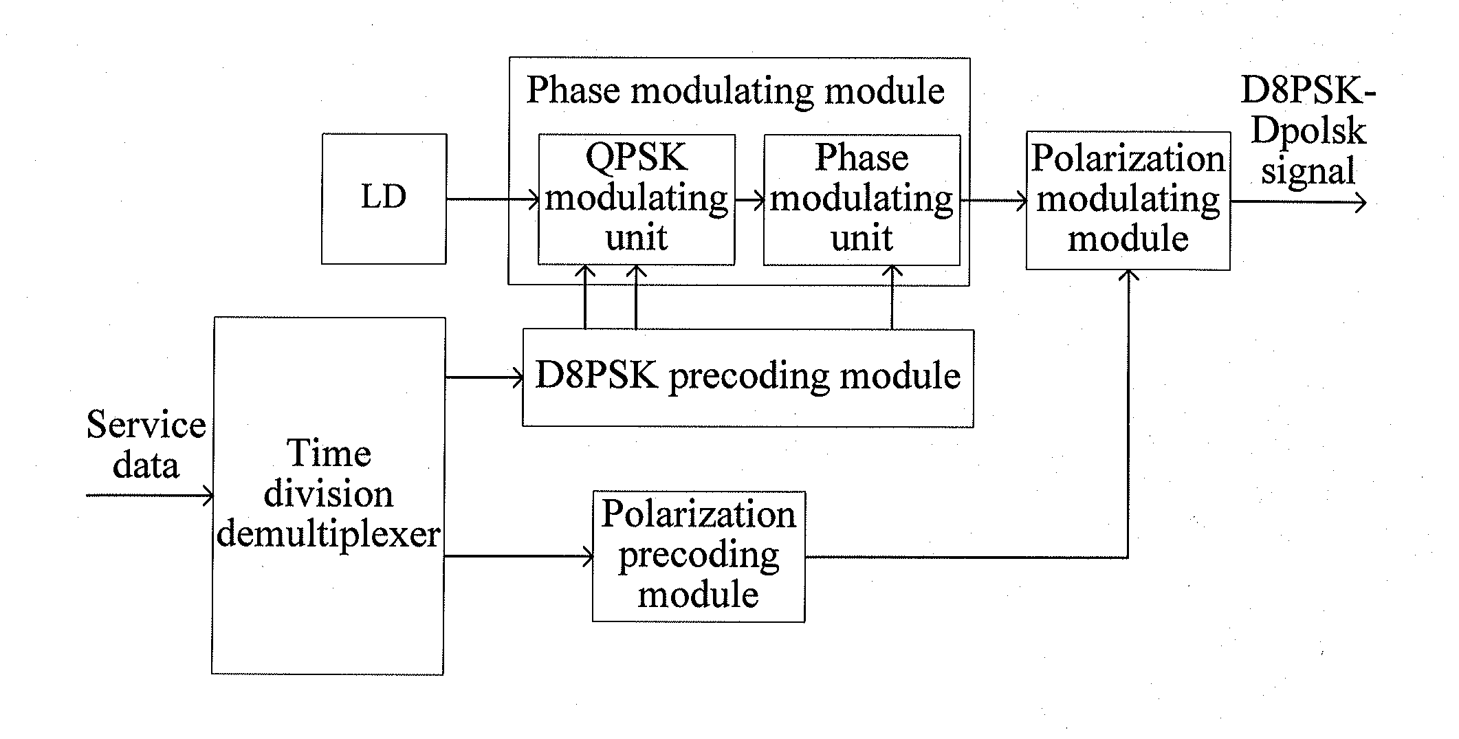
[0029]Furthermore, FIG. 6 is a schematic diagram of a device for generating a phase polarization modulated signal of the present invention. The phase precoding module is specifically a DQPSK precoding module, which is configured to perform phase precoding processing on the first sub-service data, so as to obtain phase precoded first sub-service data. The phase precoded first sub-service data is divided into two paths of phase precoded service data, which are selected in an intervening selection manner.

[0030]The phase modulating module specifically includes a QPSK modulating unit, which is configured to perform orthogonal phase modulation on the two paths of phase precoded service data, so as to output a phase modulated first sub-service data optical signal.

[0031]In this embodiment of the present invention, phase modulation and polarization modulation are combined at a signal transmitting end, so that each pulse, that is, each constellation point of the generated phase polarization ...

embodiment 4

[0032]FIG. 7 is a schematic diagram of a device for receiving a phase polarization modulated signal of the present invention, and the device includes the followings. An optical splitter is configured to receive a phase polarization modulated signal and split the received phase polarization modulated signal into a first sub-phase polarization modulated signal and a second sub-phase polarization modulated signal. A polarizer is configured to perform polarizing processing on the first sub-phase polarization modulated signal, so as to obtain a first sub-phase polarization modulated signal after being polarized. By using the birefrigent effect of a crystal, the polarizer selects a path of polarized signal of the first sub-phase polarization modulated signal. A phase demodulating and receiving unit is configured to demodulate and receive the first sub-phase polarization modulated signal after being polarized, so as to output a first sub-phase polarization modulated signal after being dem...


PUM


Abstract

In the field of communications transmission, a method, a device, and a system for generating and receiving a phase polarization modulated signal are disclosed. The device for generating the phase polarization modulated signal includes: a Laser Diode (LD), a time division demultiplexer, a phase precoding module, a phase modulating module, a polarization precoding module and a polarization modulating module. The device for receiving the phase polarization modulated signal includes: an optical splitter, a polarizer, a phase demodulating and receiving unit, a Polarization Beam Splitter (PBS), a balanced receiver, a power divider, an exclusive OR, a delayer and a data interface processing unit. Therefore, problems in the prior art that a Differential Quadrature Phase Shift Keying (DQPSK) signal cannot bear and transmit information at a higher rate and that non-linear effect is strong during transmission are solved, and transmission performance of an optical signal is improved.

Description

CROSS-REFERENCE TO RELATED APPLICATIONS[0001]This application is a continuation of International Application No. PCT / CN2010 / 071448, filed on Mar. 31, 2010, which claims priority to Chinese Patent Application No. 200910106643.3, filed on Apr. 13, 2009, both of which are hereby incorporated by reference in their entireties.FIELD OF THE INVENTION[0002]The present invention relates to the field of communications transmission, and in particular, to a method, a device and a system for generating and receiving a phase polarization modulated signal.BACKGROUND OF THE INVENTION[0003]More requirements for the capacity of a transmission network are brought forward by ever-increasing video services. A main high-end line bearer rate of a current optical transport network is 10 Gb / s, and the high-end line bearer rate of a next generation optical network is 40 Gb / s or higher than 40 Gb / s. In addition, the capacity of Ethernet services is growing at a speed of ten times, and requirements for a beare...

Claims


Application Information

Patent Timeline
Patent Type & Authority Applications(United States)
IPC IPC(8): H04J14/08H04B10/532H04B10/556H04B10/67
CPCH04B10/532H04B10/67H04B10/5561
Inventor XU, XIAOGENGLIU, LEI
Owner HUAWEI TECH CO LTD
Why Eureka
Try Eureka