Zoom lens

a zoom lens and zoom technology, applied in the field of zoom lens system, can solve the problem that the lateral magnification of the three-element cemented lens system cannot be avoided from becoming bigger, and achieve the effect of wide field angle, optimum corrected aberration, and high power variation ratio

Inactive Publication Date: 2007-05-08
KONICA MINOLTA OPTO
View PDF14 Cites 13 Cited by
  • Summary
  • Abstract
  • Description
  • Claims
  • Application Information

AI Technical Summary

Benefits of technology

[0051]In the present invention, as the first lens group has a negative refractive power and the second lens group has a positive refractive power, there can be provided a back focus wide enough to place a low-pass filter, infrared-cut filter, cover glass, and others between the shooting lens and the surface of a CCD. Further, there can be obtained an advantage of taking a great ratio of marginal light amount due to the effect of divergence of this first negative lens group when the aperture stop is located behind the negative lens group. Generally, a zoom lens system for a solid image-pickup device such as CCD is demanded to have telecentricity to get a good light-receiving sensitivity in the whole image area. Telecentricity is a special property of certain multi-element lens by which the chief rays for all points of image heights cross the object go into the imaging surface of the solid image-pickup device with an incident angle as in parallel to the optical axis as possible. Recently, although it has been possible to correct insufficient amount of telecentricity on the image side by placing a micro lens array on the imaging surface of the solid image-pickup device, the telecentricity is still insufficient. When the good telecentricity is assured, the image quality will be improved.
[0069]This invention can provide an axially-thin zoom lens which has a wide field angle, a high power variation ratio, and optimum corrected aberrations.

Problems solved by technology

When the second lens group is configured in this manner, the lateral magnification of the three-element cemented lens system cannot avoid from becoming bigger.

Method used


Image

  • Zoom lens
  • Zoom lens
  • Zoom lens

Examples


embodiment 1

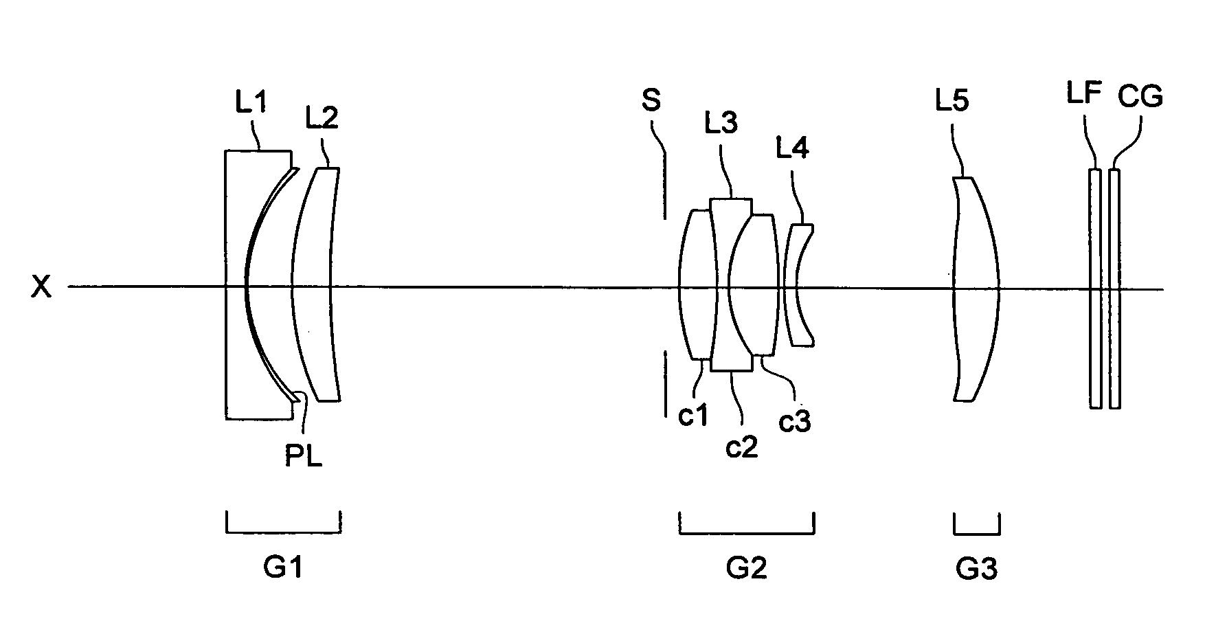
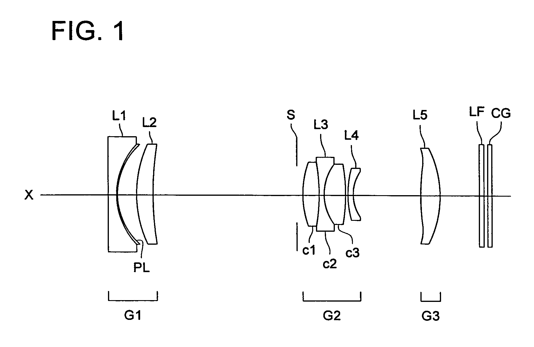
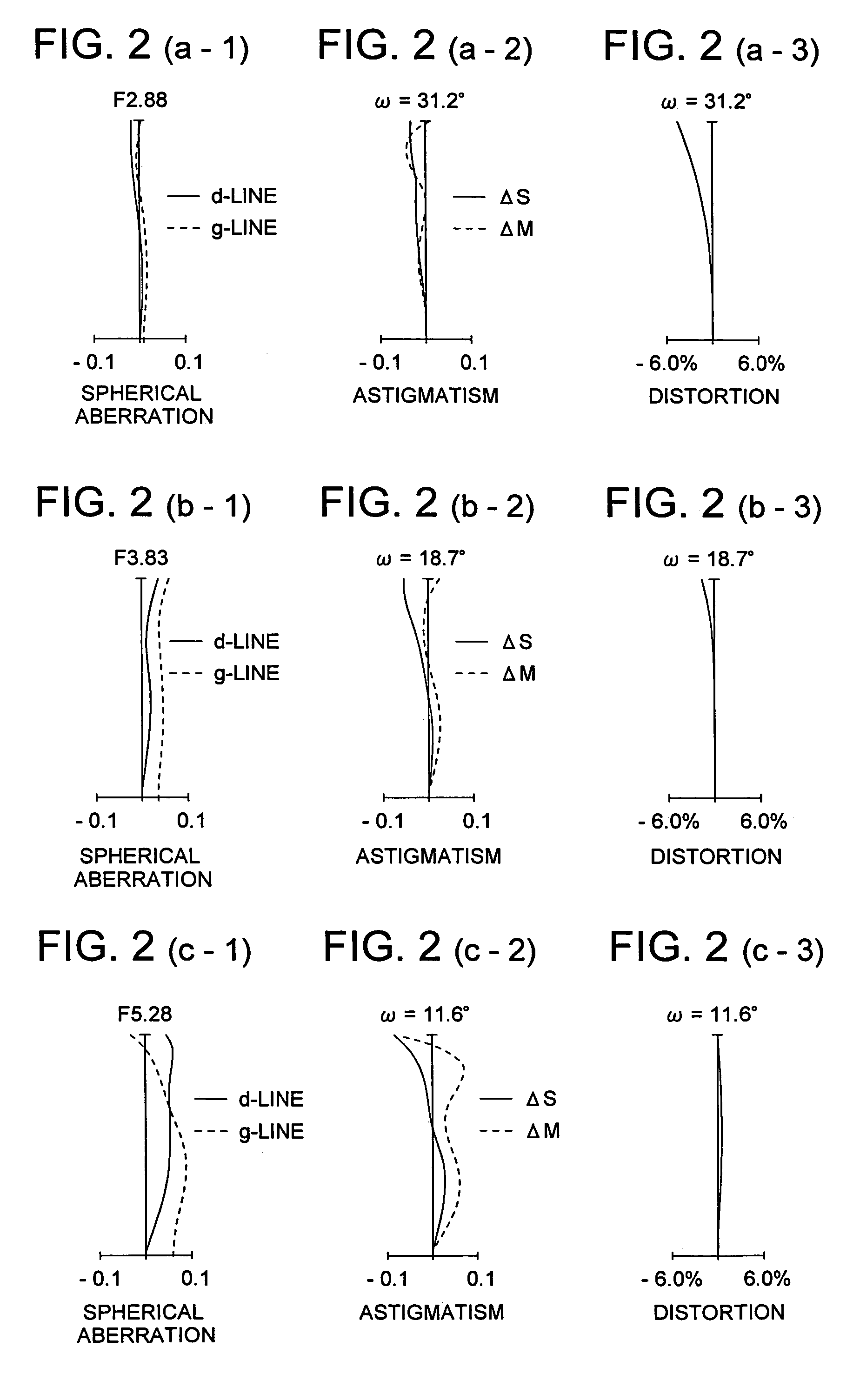
[0095]Table 1 lists lens data of the zoom lens system in accordance with Embodiment 1. FIG. 1 shows a sectional view of a zoom lens of Embodiment 1 at the wide-angle end. FIG. 2(a-1) to 2(c-3) are explanatory drawings of aberration curves such as spherical aberration, astigmatism, and distortion of a zoom lens of Embodiment 1. FIG. 2(a-1) to 2(a-3) show aberration curves of the zoom lens at the wide-angled end. FIG. 2(b-1) to 2(b-3) show aberration curves at an intermediate position. FIG. 2(c-1) to 2(c-3) show aberration curves of the zoom lens at the telephoto end. In the following aberration diagrams, solid lines represent d-lines and dotted lines represent g-lines. In the astigmatism diagrams, solid lines represent sagittal image surface and dotted lines represent meridional image surfaces.

[0096]

TABLE 1Embodiment 1SurfacenumberR (mm)d (mm)ndνd1153.0790.951.8830040.827.8470.051.5131353.936.6912.02411.8621.891.8466623.8543.804d1 (variable)68.5671.741.7680249.27−32.1460.451.6034238....

embodiment 2

[0099]Table 2 lists lens data of the zoom lens system in accordance with Embodiment 2. FIG. 3 shows a sectional view of a zoom lens of Embodiment 2 at the wide-angle end. FIG. 4(a-1) to 4(c-3) are explanatory drawings of aberration curves such as spherical aberration, astigmatism, and distortion of a zoom lens of Embodiment 2. FIG. 4(a-1) to 4(a-3) show aberration curves of the zoom lens at the wide-angle end. FIG. 4(b-1) to 4(b-3) show aberration curves at an intermediate position. FIG. 4(c-1) to 4(c-3) show aberration curves of the zoom lens at the telephoto end.

[0100]

TABLE 2Embodiment 2SurfacenumberR (mm)d (mm)ndνd187.7220.951.8160046.627.9150.051.5131353.936.9202.33411.6311.731.8466623.8527.306d1 (variable)68.2321.711.7680249.27−47.8560.451.6034238.084.9282.141.7291654.79−58.9670.2010 9.9180.551.7173629.511 4.389d2 (variable)12 30.1061.901.6935053.213 −33.255d3 (variable)14 ∞0.431.5488067.015 ∞0.3916 ∞0.501.5163364.117 ∞Aspheric surface coefficient3rd surfaceK = 0.0A4 = −3.37440...

embodiment 3

[0103]Table 3 lists lens data of the zoom lens system in accordance with Embodiment 3. FIG. 5 shows a sectional view of a zoom lens of Embodiment 3 at the wide-angle end. FIG. 6(a-1) to 6 (c-3) are explanatory drawings of aberration curves such as spherical aberration, astigmatism, and distortion of a zoom lens of Embodiment 3. FIG. 6(a-1) to 6(a-3) show aberration curves of the zoom lens at the wide-angle end. FIG. 6(b-1) to 6(b-3) show aberration curves at an intermediate position. FIG. 6(c-1) to 6(c-3) show aberration curves of the zoom lens at the telephoto end.

[0104]

TABLE 3Embodiment 3SurfacenumberR (mm)d (mm)ndνd152.7940.951.8160046.626.7642.40310.9701.761.8466623.8423.614d1 (variable)57.7021.501.6935053.26−200.0000.551.6034238.075.2752.201.7291654.78−37.0400.2099.2700.601.7173629.510 4.352d2 (variable)11 26.0401.551.6935053.212 −47.694d3 (variable)13 ∞0.401.5488067.014 ∞0.3915 ∞0.501.5163364.116 ∞Aspheric surface coefficient2nd surfaceK = 0.00000E+00A4 = −2.15460E−04A6 = −3.7...


PUM


Abstract

A zoom lens system includes a first lens group which has a negative refractive power, a second lens group which has a positive refractive power, and a third lens group which has a positive refractive power in this order from the object side and changes the distances among these lens groups to vary the power from the wide-angle end to the telephoto end. The second lens group has a three-element cemented lens including a positive lens c1, a negative lens c2, and a positive lens c3.

Description

[0001]This application is based on Japanese Patent Application No. 2005-037172 filed on Feb. 15, 2005, which is incorporated hereinto by reference.BACKGROUND OF THE INVENTION[0002]This invention relates to a zoom lens system for a digital camera, video camera or the like, particularly to a compact and axially-thin zoom lens system of, for example, a power variation ratio of 3 and a field angle of 60° or more at a wide-angle end which is fit for CCD (charge coupled device) and CMOS (complementary metal-oxide semiconductor).[0003]Recently, there have been lots of digital still cameras and video camera which use CCDs or CMOSs. Particularly, only thin cameras have enjoyed an increasing demand. A three-element cemented lens system whose axial length is suppressed has been disclosed for such thin cameras. (See Patent Document 1.)[0004][Patent Document 1] Japanese Non-Examined Patent Publication 2004-325975[0005]The second lens group of the zoom lens system of Patent Document 1 is composed...

Claims


Application Information

Patent Timeline
Patent Type & Authority Patents(United States)
IPC IPC(8): G02B15/14
CPCG02B15/177G02B15/143507
Inventor YAMASHITA, ATSUSHINOBE, SHINSUKE
Owner KONICA MINOLTA OPTO
Why Eureka
Try Eureka