Combined channel coding and space-time block coding in a multi-antenna arrangement

a technology of combined channel coding and space-time block coding, applied in the field of wireless communication, can solve the problems of limited system capacity, power limitation, size and speed of devices employed in portable wireless devices, and physical limitations of wireless channels, so as to improve performance, increase system capacity, and improve performan

Inactive Publication Date: 2007-05-08
AMERICAN TELEPHONE & TELEGRAPH CO
View PDF10 Cites 28 Cited by
  • Summary
  • Abstract
  • Description
  • Claims
  • Application Information

AI Technical Summary

Benefits of technology

[0015]Enhanced performance is achieved by combining channel coding with the space-time coding principles disclosed in the '163 applications. More specifically, with K synchronized terminal units transmitting on N antennas to a base station having M≧K receive antennas, increased system capacity and improved performance are attained by using a concatenated coding scheme where the inner code is a space-time block code and the outer code is a conventional channel error cor

Problems solved by technology

Physical limitations of wireless channels present a fundamental technical challenge to reliable communication.
Bandwidth limitations, propagation loss, time variance, noise, interference, and multipath fading make the wireless channel a narrow “pipe” that does not easily accommodate the flow of data.
Further challenges come from power limitation, size, and speed of devices that are employed within portable wireless app

Method used


Image

  • Combined channel coding and space-time block coding in a multi-antenna arrangement
  • Combined channel coding and space-time block coding in a multi-antenna arrangement
  • Combined channel coding and space-time block coding in a multi-antenna arrangement

Examples


Embodiment Construction

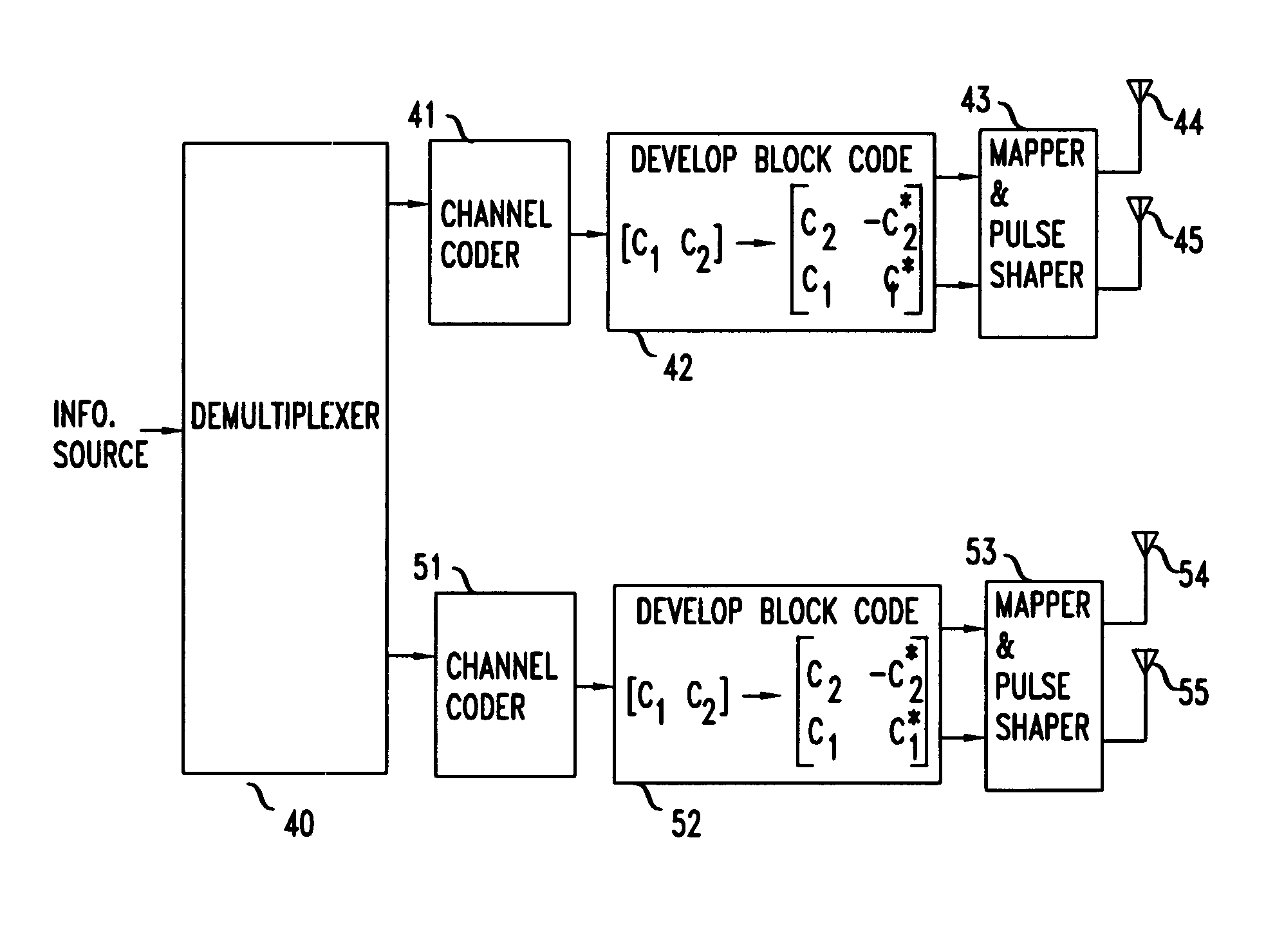
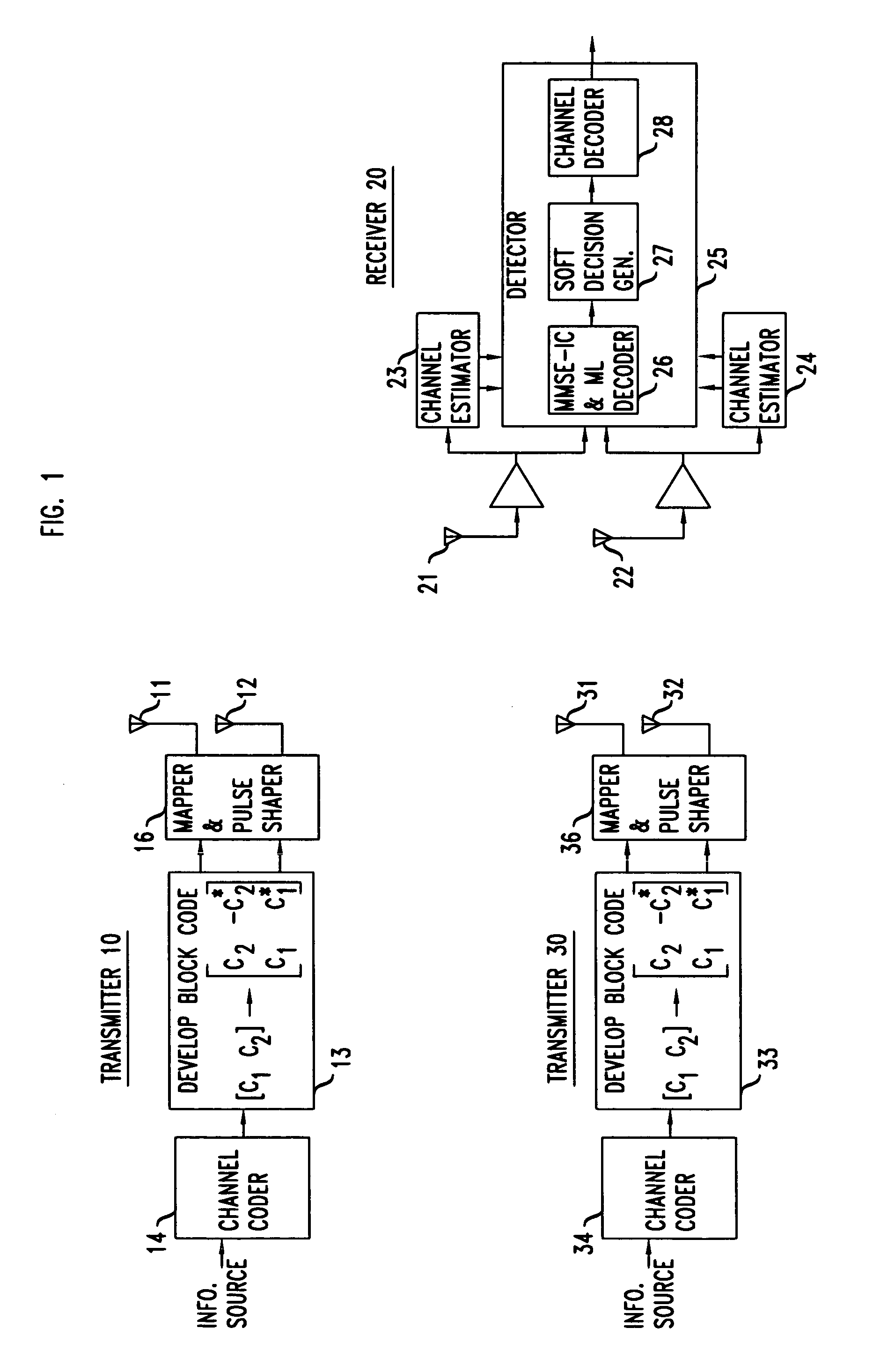
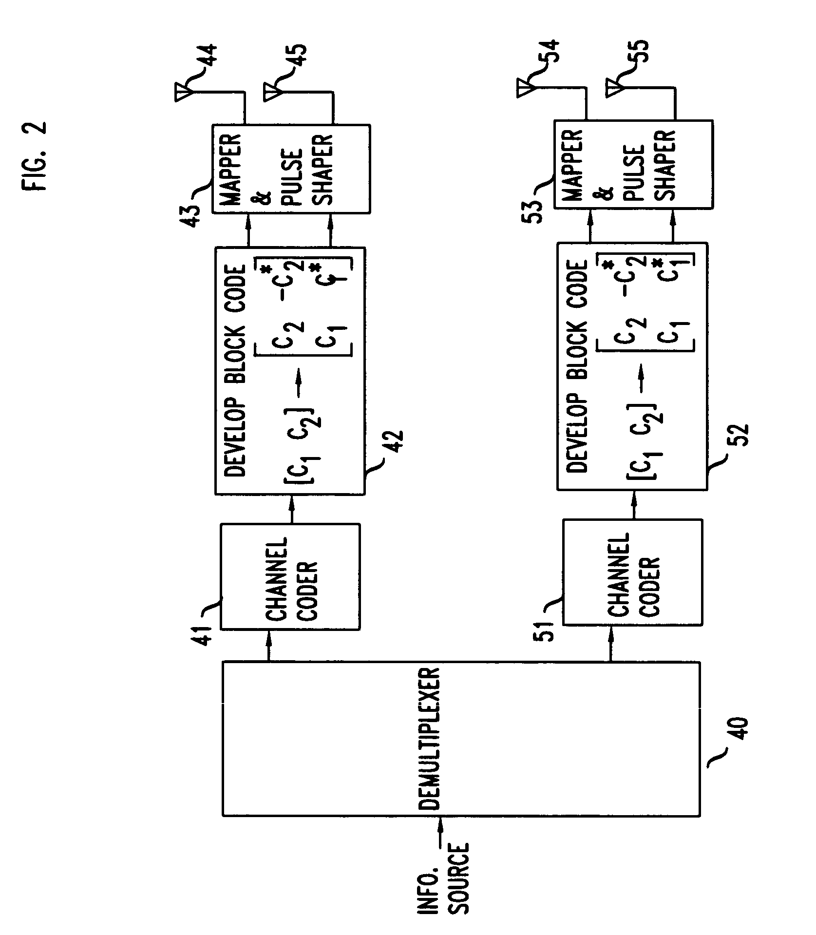
[0019]FIG. 1 illustrates a unit 10 that employs a space-time block coding unit 13 that is followed by a conventional constellation mapper and pulse shaping circuit 16. The output of circuit 16 is fed to two transmitting antennas 11 and 12. The input symbols to the space-time block encoder are divided into groups of two symbols each, and at a given symbol period, the two symbols in each group {c1, c2} are transmitted simultaneously from the two antennas. The signal transmitted from antenna 11 is c1 and the signal transmitted from antenna 12 is c2. In the next symbol period, the signal −c2* is transmitted from antenna 11 and the signal c1* is transmitted from antenna 12.

[0020]In receiver 20, signals are received by antennas 21 and 22 and are applied to detector 25. Channel estimators 23 and 24 operate on the incoming signal of antennas 21 and 24, respectively, in a conventional manner to develop estimates of the channel parameters. Those estimates are applied to detector 25. In the ma...


PUM


Abstract

Enhanced performance is achieved by combining channel coding with the space-time coding principles. With K synchronized terminal units transmitting on N antennas to a base station having M≧K receive antennas, increased system capacity and improved performance are attained by using a concatenated coding scheme where the inner code is a space-time block code and the outer code is a conventional channel error correcting code. Information symbols are first encoded using a conventional channel code, and the resulting signals are encoded using a space-time block code. At the receiver, the inner space-time block code is used to suppress interference from the other co-channel terminals and soft decisions are made about the transmitted symbols. The channel decoding that follows makes the hard decisions about the transmitted symbols. Increased data rate is achieved by, effectively, splitting the incoming data rate into multiple channels, and each channel is transmitted over its own terminal.

Description

REFERENCE TO RELATED APPLICATIONS[0001]This application is related to:[0002]U.S. application Ser. No. 09 / 074,224, filed May 7, 1998, titled “Transmitter Diversity Technique for Wireless Communications,” which is based U.S. Provisional Applications No. 60 / 059,016 filed Sep. 16, 1997; 60 / 059,219 filed Sep. 18, 1997; and 60 / 063,780 filed Oct. 31, 1997;[0003]U.S. application Ser. No. 09 / 149,163 filed Sep. 4, 1999, titled “Combined Interference Cancellation and Maximum Likelihood Decoding of Block Space-Time Coded Modulation,” which is based on U.S. Provisional Application No. 60 / 061,145, filed Oct. 6, 1997; and[0004]U.S. application Ser. No. 09 / 114,838, filed Jul. 14, 1998, titled “Combined Array Processing and Space-Time Coding,” which is based on U.S. Provisional Application No. 60 / 052,689, filed Jul. 17, 1997.This application claims the benefit of U.S. Provisional Application No. 60 / 099,212, filed Sep. 4, 1998.BACKGROUND OF THE INVENTION[0005]This invention relates to wireless commun...

Claims


Application Information

Patent Timeline
IPC IPC(8): H04L27/04
CPCH04L1/0625H04L1/0643
Inventor CALDERBANK, ARTHUR ROBERTNAGUIB, AYMANSESHADRI, NAMBIRAJAN
Owner AMERICAN TELEPHONE & TELEGRAPH CO
Why Eureka
Try Eureka