Method and apparatus for mitigation of modal dispersion effects in multimode fiber

a multi-mode fiber and modal dispersion technology, applied in the field of fiber optic communication, can solve the problems the principal limitation factor of intersymbol interference caused by modal dispersion, and the cost of reducing the resulting degradation of the bit rate-distance product due to isi, so as to reduce the effect of intersymbol interference, the effect of modal dispersion

Inactive Publication Date: 2007-05-08
LOCKHEED MARTIN CORP
View PDF9 Cites 2 Cited by
  • Summary
  • Abstract
  • Description
  • Claims
  • Application Information

AI Technical Summary

Problems solved by technology

This temporal pulse distortion, or modal dispersion, results in what is known as intersymbol interference (ISI) at the receiver or signal detector.
Intersymbol interference caused by the modal dispersion is the principal limiting factor affecting what is known as the bit rate-distance product of the fiber communication system.
However, many of the existing legacy fiber installations found, for example, on ships, in aircraft and throughout local area networks consist of multimode, premises optical fiber that cannot be replaced by single mode fiber in a cost effective manner.
However, both of the above mentioned techniques for mitigating modal dispersion in multimode fiber and reducing the resulting degradation of the bit rate-distance product due to ISI are costly and technically complex.

Method used


Image

  • Method and apparatus for mitigation of modal dispersion effects in multimode fiber
  • Method and apparatus for mitigation of modal dispersion effects in multimode fiber
  • Method and apparatus for mitigation of modal dispersion effects in multimode fiber

Examples


Embodiment Construction

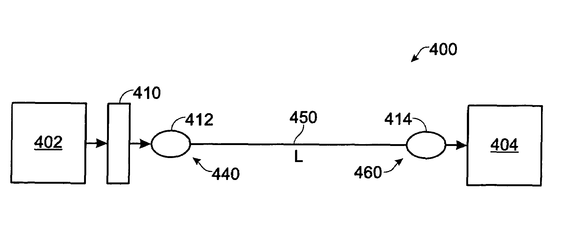
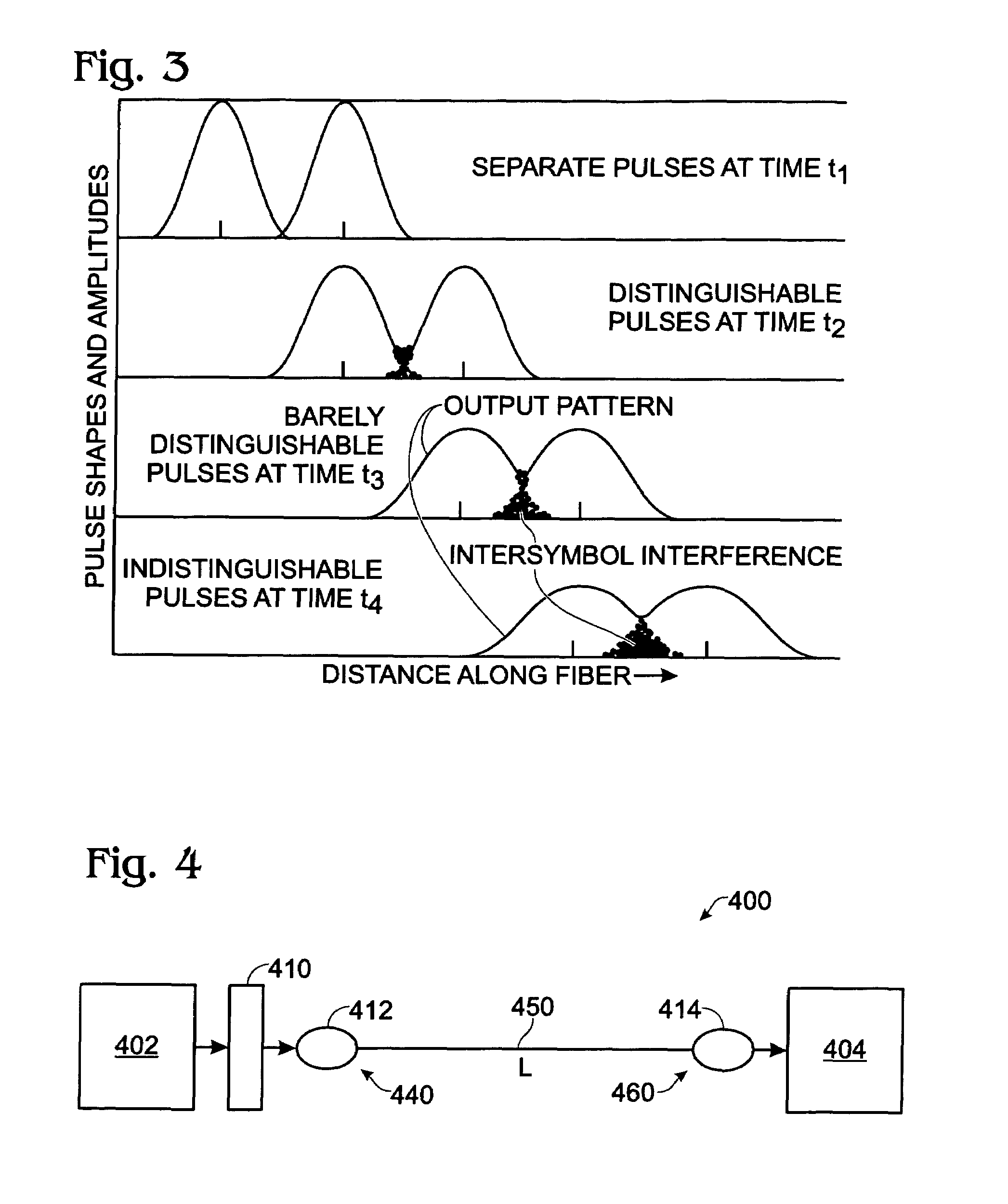
[0020]A method for mitigating modal dispersion of an optical signal in a multimode optical fiber transmission medium involves the steps of providing an optical signal, transforming the optical signal into a form characterized as a Bessel beam, launching the Bessel beam signal into an input end of a multimode optical fiber transmission medium, outputting the optical signal at an output end of the multimode optical fiber transmission medium and receiving the output signal at a receiving station of the transmission system. The diffractionless nature of Bessel beam propagation allows the launch or excitation of signal transmission modes in the multi-mode optical fiber that are less prone to temporal spreading, known in the art as modal dispersion, which results in intersymbol interference at a detector or receiver in the system, and which limits the bit rate-distance product capacity of the system. Embodiments of the invention are applicable to all common fiber optical communication tra...


PUM


Abstract

A method for mitigating modal dispersion in a multimode optical fiber involves launching a diffractionless optical beam, such as a Bessel beam, into a multimode optical fiber. A fiber optical transmission system includes a multimode optical fiber transmission medium having an input end and an output end, an optical signal transmitter in communication with the input end of the multimode optical fiber medium, means for converting the optical signal into a diffractionless optical signal, means for launching the diffractionless optical signal in the input end of the multimode optical fiber transmission medium, means for outputting the propagated optical signal from an output end of the multimode fiber transmission medium, and a receiver that receives the optical signal from the output means. Fiber optic communication systems employing the invention embodiments include point-to-point transmission links, local area networks and WDM systems including coarse wavelength division multiplexing and dense wavelength division multiplexing systems.

Description

RELATED APPLICATION DATA[0001]This application is related to U.S. provisional application Ser. No. 60 / 623,671 filed on Oct. 29, 2004 and incorporated herein by reference in its entirety, and claims the benefit of priority thereto under 35 USC §119(e).BACKGROUND OF THE INVENTION[0002]1. Field of the Invention[0003]Embodiments of the invention are generally directed to the field of fiber optic communication and more particularly to a method and apparatus for mitigating the effects of modal dispersion in multimode optical fiber and fiber optic communication systems incorporating these methods and apparatus.[0004]2. Description of Related Art[0005]It is known to propagate optical communication signals over the medium known as optical fiber. The most general types of optical fiber are referred to as single mode fiber and multimode fiber. Optical fiber generally consists of two parts: a core region and a cladding region surrounding the core region. The core region and the cladding region ...

Claims


Application Information

Patent Timeline
Patent Type & Authority Patents(United States)
IPC IPC(8): G02B6/26
CPCH04B10/2581H04J14/02
Inventor WERNER, WALTER V.LAVIOLETTE, KERRY D.
Owner LOCKHEED MARTIN CORP
Why Eureka
Try Eureka