
Internal combustion engine provided with double system of fuel injection

a technology of fuel injection and combustion engine, which is applied in the direction of combustion-air/fuel-air treatment, electric control, ignition automatic control, etc., can solve the problems of inability to achieve optimum ignition timing and damage to the combustion chamber, so as to avoid the generation of knocking through easy arithmetic (operational) processing, avoid defects, and achieve optimal ignition timing

Active Publication Date: 2007-05-15
TOYOTA JIDOSHA KK +1
View PDF80 Cites 17 Cited by
  • Summary
  • Abstract
  • Description
  • Claims
  • Application Information

AI Technical Summary

Benefits of technology

[0012]An object of the present invention is therefore to substantially eliminate defects or drawbacks encountered in the prior art publication mentioned above and to provide an internal combustion engine which has double system of fuel injection including both PFI system and DI system and is capable of avoiding the generation of knocking through easy arithmetic (operation) processing and realizing an optimum ignition timing.
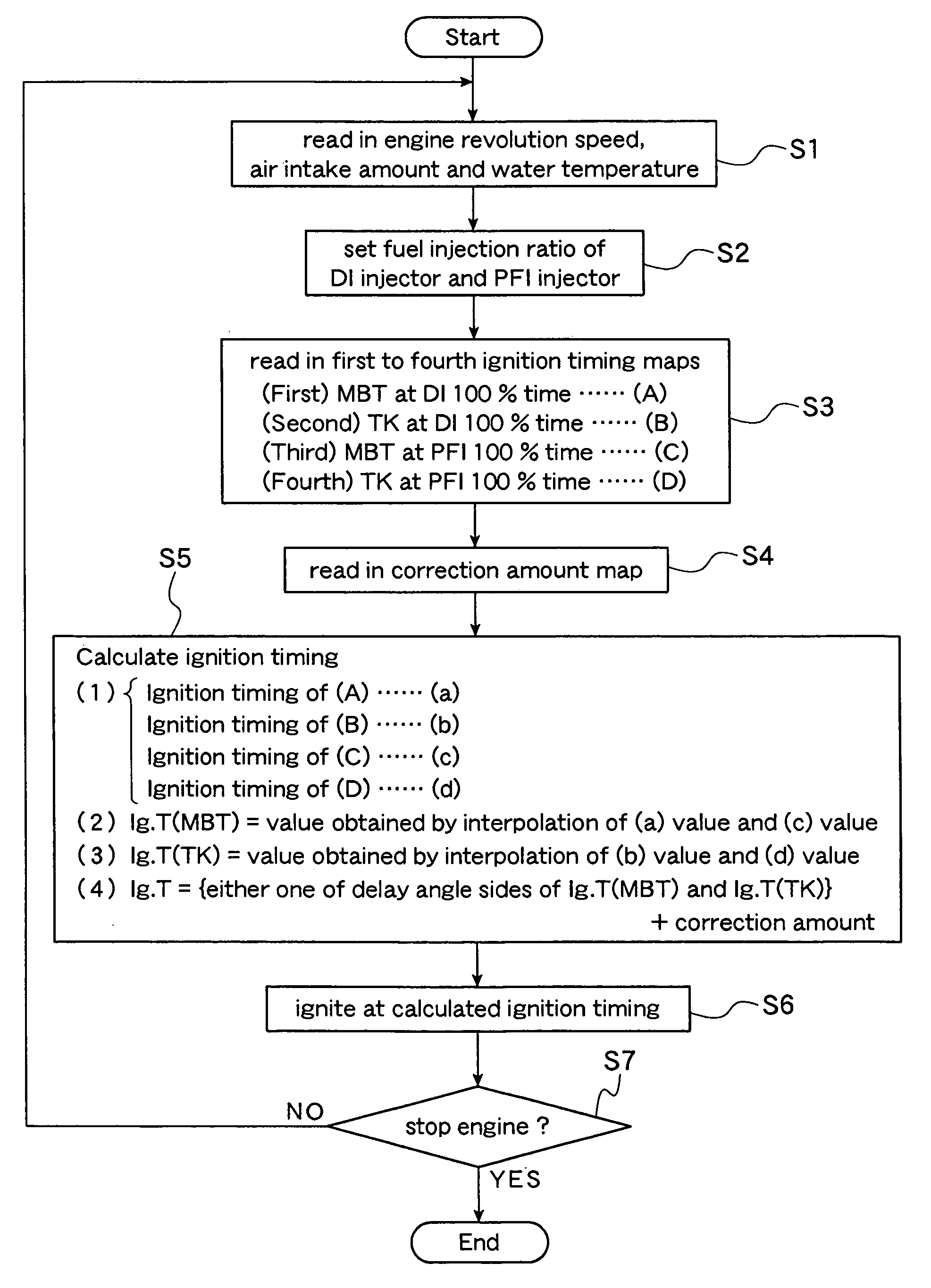
[0024]According to the structures and characters of the present invention mentioned above, by controlling the ignition timing with reference to the first to fourth ignition timing maps, the ignition timing can correspond, through easy calculation processing, to the direct injection system and port fuel injection system which are different in the maximum torque generation timing and the knocking limit torque generation timing. Therefore, in the internal combustion engine provided with double system of fuel injection, i.e. direct injection injector and port fuel injection injector, the generation of the knocking can be avoided with the easy operation processing, and thereby, an optimum ignition timing can be set.
[0025]According to the preferred embodiment of the present invention, in the internal combustion engine provided with double system of fuel injection, i.e. direct injection injector and the port fuel injection injector, the ignition timing can be always regulated and maintained to a condition suitable for the optimum operation of the internal combustion engine, the generation of the knocking can be avoided, and hence, the optimum ignition timing can be set only by utilizing the four sheets of ignition timing maps even in the case where the engine is operated under the regulation of the fuel injection quantity of the direct injection injector and the port fuel injection injector in accordance with the operating condition of the engine without performing complicated calculation operation.
[0026]In addition, according to the present embodiment, the engine operating condition can be detected by the engine revolution detector and the engine load detector, and therefore, the ignition timing can be controlled with reference to the parameters of the engine revolution speed and the engine load, thus realizing the optimum ignition timing control with high precision.
[0027]Furthermore, in the case of the location of at least either one of an intake air amount detector, an accelerator opening detector and an intake pipe negative pressure detector, the load amount applied to the engine can be precisely detected and, hence, the ignition timing can be accurately controlled.
[0028]Still furthermore, the location of the cooling water temperature detector enables the calculation of the correction amount of the ignition timing and adjustment of the ignition timing based on the warm-up condition of the engine, thus enhancing the controlling performance to the ignition timing.

Problems solved by technology

According to the generation of such knocking, temperature and pressure in the combustion chamber are abnormally increased, which may cause damage to the combustion chamber.
Therefore, even if the invention of the above-mentioned prior art patent publication is applied to the case in which both systems are parallelly arranged for each cylinder of the engine, an optimum ignition timing cannot be achieved.

Method used


Image

  • Internal combustion engine provided with double system of fuel injection
  • Internal combustion engine provided with double system of fuel injection
  • Internal combustion engine provided with double system of fuel injection

Examples


Embodiment Construction

[0039]One preferred embodiment according to the present invention will be described hereunder with reference to the accompanying drawings.

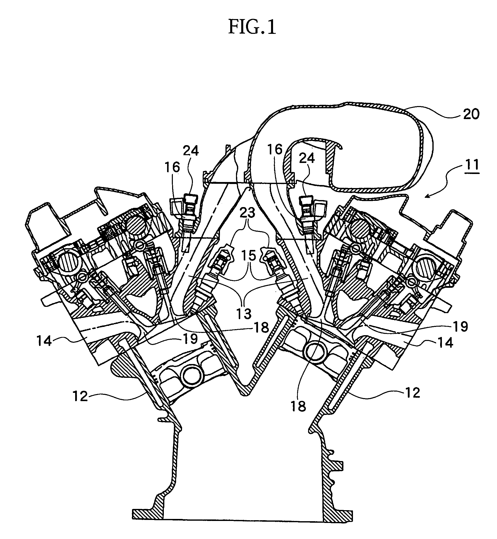
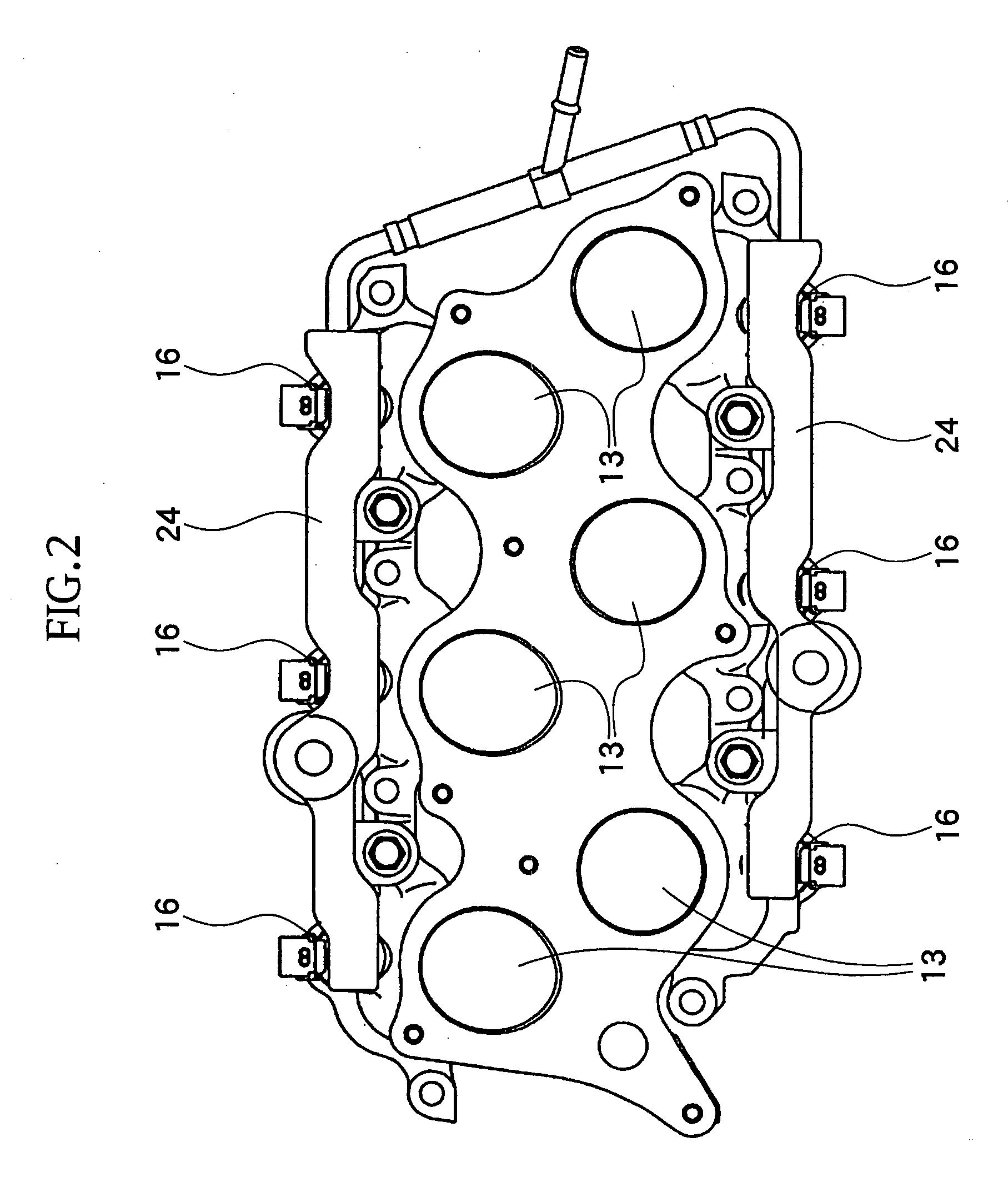
[0040]With reference to FIGS. 1 to 8, reference numeral 11 denotes a V-type 6-cylinder engine as an internal combustion engine (which may be called hereinlater merely “engine”) of the present invention, in which an intake port 13 and an exhaust port 14 are connected to each of the cylinders 12, which is in addition provided with a direct injection-type injector (DI injector) 15 and a port fuel injection-type injector (PFI injector) 16.

[0041]The fuel is directly injected into the cylinder, i.e., combustion chamber 12 from the DI injector 15 and is then mixed with air in the cylinder 12, and in addition, the fuel is injected into the intake port 13 through the PFI injector 16 and is then mixed with air passing in the intake port 13. The thus mixed fuel is sucked in the cylinder 12 and burnt therein by an ignition of an ignition plug 14a, not shown, ...


PUM


Abstract

An internal combustion engine includes an engine control unit for setting a ratio of fuel injection quantity of both the injectors. The engine control unit includes a memory storing four sheets of ignition timing maps, with reference to which the maximum torque generation timing and knocking limit torque generation timing, at the direct injection injector (100%) and port fuel injection injector (100%), are calculated. The engine control unit further operates to calculate a correction amount from correction amount map, and calculates first interpolation value of the maximum torque generation timing at the above 100% operation time of both the injectors and second interpolation value of the knocking limit torque generation timing at the above 100% operation time of both the injectors. A value in which the correction amount is added to either one of the above first and second interpolation value on a delay angle side is calculated as ignition timing.

Description

CROSS REFERENCE TO RELATED APPLICATION[0001]This application is based upon and claims the benefit of priority from prior Japanese Patent Application No. 2005-080698 filed on Mar. 18, 2005, the entire contents of which are incorporated herein by reference.BACKGROUND OF THE INVENTION[0002]1. Field of the Invention[0003]The present invention relates to an internal combustion engine provided with double system of fuel injection including a port fuel injection (PFI) system and a direct injection (DI) system.[0004]2. Related Art[0005]In an internal combustion engine of an automobile, a knocking may be caused at a time when an automobile is rapidly accelerated from a low speed running thereof.[0006]The knocking is a phenomenon in which unburned fuel-air mixture in front of a propagation flame is compressed to a high temperature and then self-ignited due to incompatibility between engine load and engine ignition timing, and a large pressure wave generated at a combustion period in a combust...

Claims


Application Information

Patent Timeline
Patent Type & Authority Patents(United States)
IPC IPC(8): F02P5/15F02B15/00F02D43/04
CPCF02D41/3094F02M35/10085F02M35/10177F02M35/10216F02M35/116F02M63/0225F02M63/029F02M63/0295F02M69/046F02P5/1514F02P5/152F02B23/104F02B2075/125F02B2275/16F02M69/044F02M69/465Y02T10/46Y02T10/123Y02T10/12Y02T10/40F02P5/15F02M63/00F02D41/34
Inventor ITO, YUKIKAZUIWAMI, YUTAKANISHIGAKI, MASATO
Owner TOYOTA JIDOSHA KK
Learn More