RF microwave connector for telecommunication

a technology of rf microwave connector and telecommunication, which is applied in the direction of connections, basic electric elements, electric devices, etc., can solve the problems of labor and time consumption, and achieve the effect of enhancing good product rate, convenient and cheap manufacturing, and reducing the ratio of bad product ra

Inactive Publication Date: 2007-05-15
INSERT ENTERPRISE
View PDF5 Cites 47 Cited by
  • Summary
  • Abstract
  • Description
  • Claims
  • Application Information

AI Technical Summary

Benefits of technology

[0010]For improving the combination structure of a terminal of a plug of a coaxial microwave connector and inner wires of a coaxial cable, allowing the manufacturing more convenient and cheap and enabling the ratio of bad product rate to be lowered down, the present invention is proposed.
[0011]The main object of the present invention is to provide a RF microwave connector for telecommunication, enabling a manufacturing combination between a female terminal of a plug and inner wires of a coaxial cable to be easier.
[0012]Another object of the present invention is to provide a RF microwave connector for telecommunication, enabling a female terminal of a plug to be combined with inner wires of a coaxial cable tightly and not to loose so as to enhance the good product rate.
[0013]Still another object of the present invention is to provide a RF microwave connector for telecommunication, even if using simpler and cheaper machine, a female terminal of a plug and inner wires of a coaxial cable can be combined tightly.

Problems solved by technology

The manufacturing way welding the coaxial cable and the female terminal manually mentioned above cannot be replaced with an automatic machine manufacturing way, it is labor and time wasting.

Method used


Image

  • RF microwave connector for telecommunication
  • RF microwave connector for telecommunication
  • RF microwave connector for telecommunication

Examples


Embodiment Construction

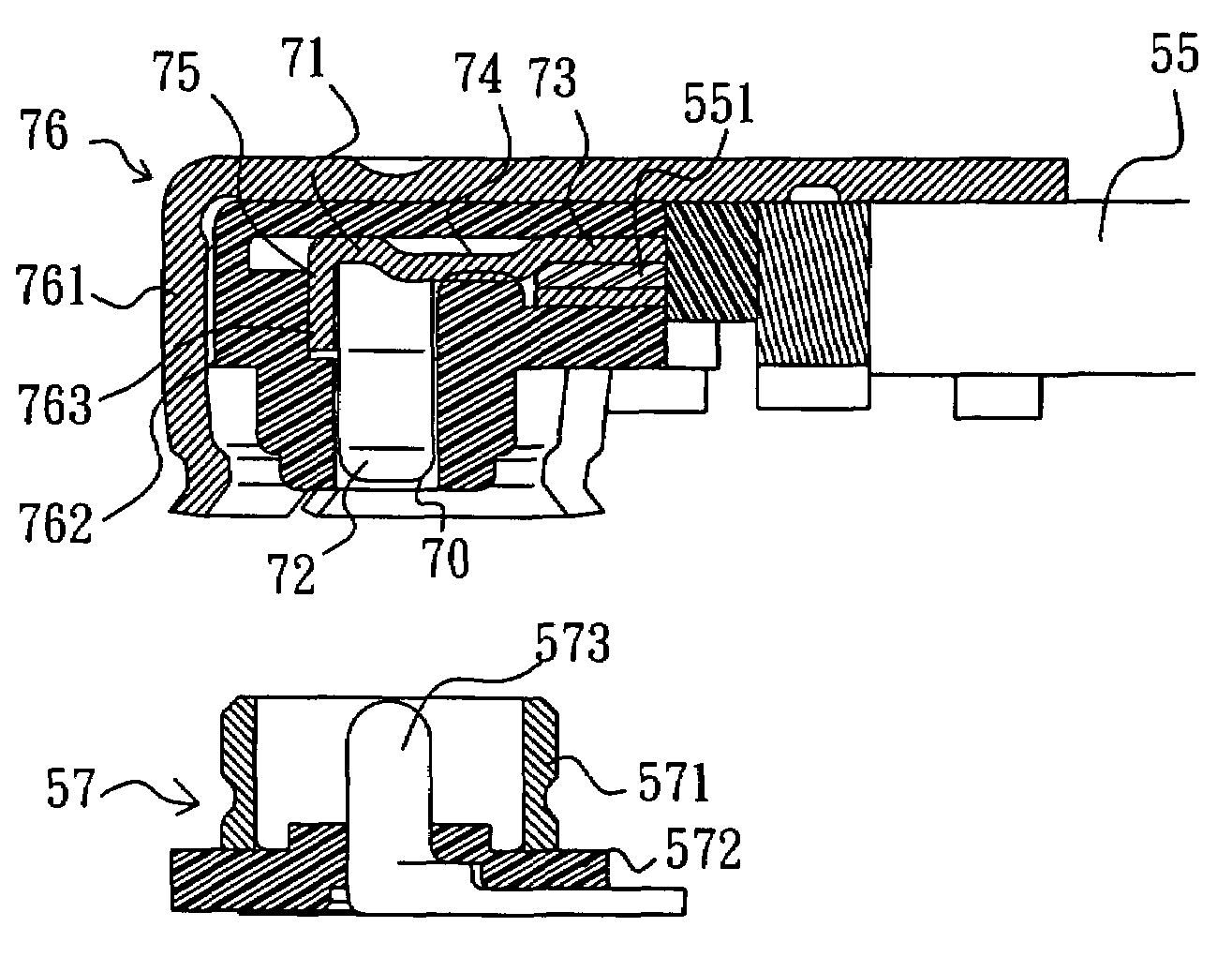
[0033]Please refer to FIGS. 5A to 5E. A female terminal 50 of a first preferred embodiment according to the present invention has a main body 51. Two opposite contact plates 52 are extended from the two sides of one end of the main body 51 used for combining with a male terminal. An arc shape of clamping section 53 is disposed at another end of the main body 51 and a groove hole 531 is disposed in the arc face of the clamping section 53. Two edges 532 and 533 of the clamping section 53 are symmetrically arched. A strip type of raised portion 54 is disposed on the surface of the inner side of the main body 51 close to the clamping section 53 and the raised portion 54 is extended between the contact plates 52.

[0034]The design that the two edges 532 and 533 of the clamping section 53 of the terminal 50 are symmetrically arched in the preferred embodiment is suitable for using only a simpler and cheaper manufacturing machine, the edges 532 and 533 can be bended face to face smoothly to ...


PUM


Abstract

A RF microwave connector for telecommunication comprises a plug; a metal housing of the plug is combined with an insulator; a female terminal is combined with the hollow portion of the insulator; the female terminal has a main body, two opposite contact plates are extended from two sides of one end of the main body for clamping a male terminal; an arc shape of clamping section is disposed at another end of the main body, two edges of the clamping section are symmetrically arched so as to allow the edges of the clamping section to be bended oppositely smoothly to clamp inner wires of a coaxial cable stably when that the clamping section is combined with the inner wires is processed.

Description

BACKGROUND OF THE INVENTION[0001]1. Field of the Invention[0002]The present invention relates to an electric connector, and more particularly to a RF (Radio Frequency) microwave connector for telecommunication.[0003]2. Description of Related Art[0004]Please refer to FIGS. 1A and 1B. A conventional coaxial microwave connector consists of a plug and a receptacle, in which the plug has a female terminal 10. Two opposite contact plates 11 are disposed at one side of the female terminal 10 and a stop plate 12 is disposed at another side thereof. A slit 121 exists in the stop plate 12. The contact plates 11 are used to clamp a male terminal of the receptacle. The slit 121 is used to allow the inner wires 131 of a coaxial cable 13 to be passed through it and welded on the upper side of the female terminal 10, as FIG. 1B shows.[0005]Please refer to 2A and 2B. Another conventional coaxial microwave connector, a plug thereof has a female terminal 20. Two opposite contact plates 21 are dispose...

Claims


Application Information

Patent Timeline
Patent Type & Authority Patents(United States)
IPC IPC(8): H01R9/05
CPCH01R4/188H01R4/184
Inventor WANG, SHUN-PING
Owner INSERT ENTERPRISE
Why Eureka
Try Eureka