Melamine fruit-shaped plate and production method thereof
A melamine and fruit-shaped technology is applied to the melamine fruit-shaped plate and its production field, which can solve the problem of inconvenience of holding food and dry ice at the same time on the plate, and achieve the effect of convenient combination structure.
- Summary
- Abstract
- Description
- Claims
- Application Information
AI Technical Summary
Problems solved by technology
Method used
Image
Examples
Embodiment 1
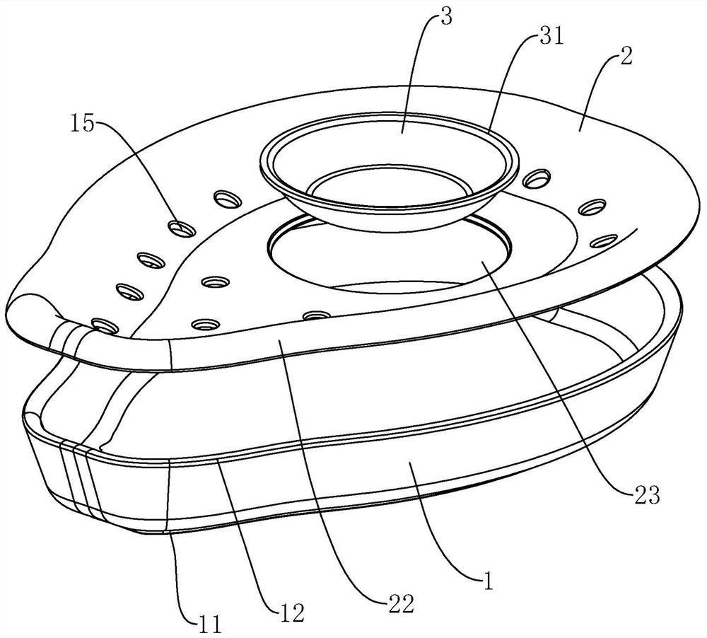
[0040] Embodiment 1: The embodiment of this application discloses a melamine fruit-shaped dish. refer to figure 1 , a melamine fruit-shaped dish, comprising a chassis 1, a tray 2 and a flavor dish 3, the chassis 1, the tray 2 and the flavor dish 3 are all made of melamine.
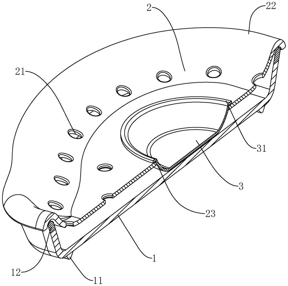
[0041] refer to figure 2 , for the beauty and comfort of the dinner plate, the chassis 1 can be provided with a fruit-shaped structure. A ring of flanges 11 is formed on the outer bottom wall of the chassis 1 , which is beneficial to support the chassis 1 . The edge of the chassis 1 has a rim 12 . The bottom of the tray 2 is provided with a number of through holes 21 for communicating with the space between the inner bottom wall of the chassis 1 and the bottom of the tray 2. There is a flanging portion 22 on the edge of the tray 2, and the flanging portion 22 is fastened to the edge 12, which can Complete the connection between tray 2 and chassis 1. The bottom of the tray 2 is provided with a placemen...
Embodiment 2
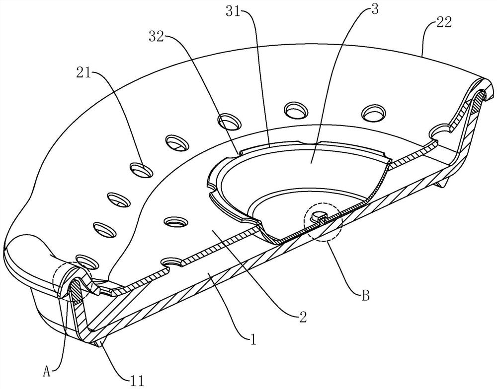
[0049] Embodiment 2: refer to image 3 , Figure 4 , the difference from Embodiment 1 is that a circle of first sealing strip 13 is fixed on the outer wall of the edge 12, and a second sealing strip 24 is fixed on the side of the flange portion 22 close to the outer wall of the edge 12, and the first sealing strip 13 The cross-sections of the second sealing strip 24 are semicircular. After the flange portion 22 is buckled on the edge 12 , the second sealing strip 24 is located above the first sealing strip 13 and abuts against the first sealing strip 13 . A plurality of grooves 32 are formed in the circumferential direction of the overlapping edge 31 , and the plurality of grooves 32 are arranged at intervals along the circumferential direction of the overlapping edge 31 .
[0050] refer to image 3 , Figure 5 The inner bottom wall of the chassis 1 is formed with a threaded column 14, and the outer bottom wall of the flavor plate 3 is concave to form a threaded groove 33,...
Embodiment 3
[0052] Embodiment 3: refer to Image 6 , Figure 7 , The difference from Embodiment 2 is that the bottom of the taste dish 3 is fixed with a suction cup 34, and the suction cup 34 is made of rubber material. A jack 15 is provided at the bottom of the chassis 1, and a soft plug 16 is inserted into the jack 15, and the soft plug 16 is made of rubber material. When installing the taste dish 3, insert the taste dish 3 into the placement hole 23, and press the taste dish 3 so that the suction cup 34 of the taste dish 3 is adsorbed on the inner bottom wall of the chassis 1, and the axis of the insertion hole 15 Coinciding with the center line of the suction cup 34 , the lapping edge 31 of the flavor dish 3 abuts against the inner bottom wall of the tray 2 . When the taste dish 3 needs to be taken off, the cork 16 is pulled out from the outer bottom of the chassis 1 to reduce the adsorption force between the suction cup 34 and the chassis 1, so that the taste dish 3 is easy to take...
PUM
 Abstract
Description
Claims
Application Information
 - R&D
- Intellectual Property
- Life Sciences
- Materials
- Tech Scout
- Unparalleled Data Quality
- Higher Quality Content
- 60% Fewer Hallucinations
Browse by: Latest US Patents, China's latest patents, Technical Efficacy Thesaurus, Application Domain, Technology Topic, Popular Technical Reports.
© 2025 PatSnap. All rights reserved.Legal|Privacy policy|Modern Slavery Act Transparency Statement|Sitemap|About US| Contact US: help@patsnap.com


