
Wire-cut electric discharge machine

a wire-cutting machine and electric discharge technology, which is applied in the direction of metal-working equipment, manufacturing tools, electrical-based machining equipment, etc., can solve the problems of inability to carry out automatic connection of wire electrodes with certainty, inability to change the contact pressure between the wire electrode and the conducting member, and the wire electrode can break, so as to reduce the production of minute electric discharges, reduce unnecessary load, and maintain friction between the moving member and the wire electrode

Inactive Publication Date: 2007-05-15
FANUC LTD
View PDF19 Cites 0 Cited by
  • Summary
  • Abstract
  • Description
  • Claims
  • Application Information

AI Technical Summary

Benefits of technology

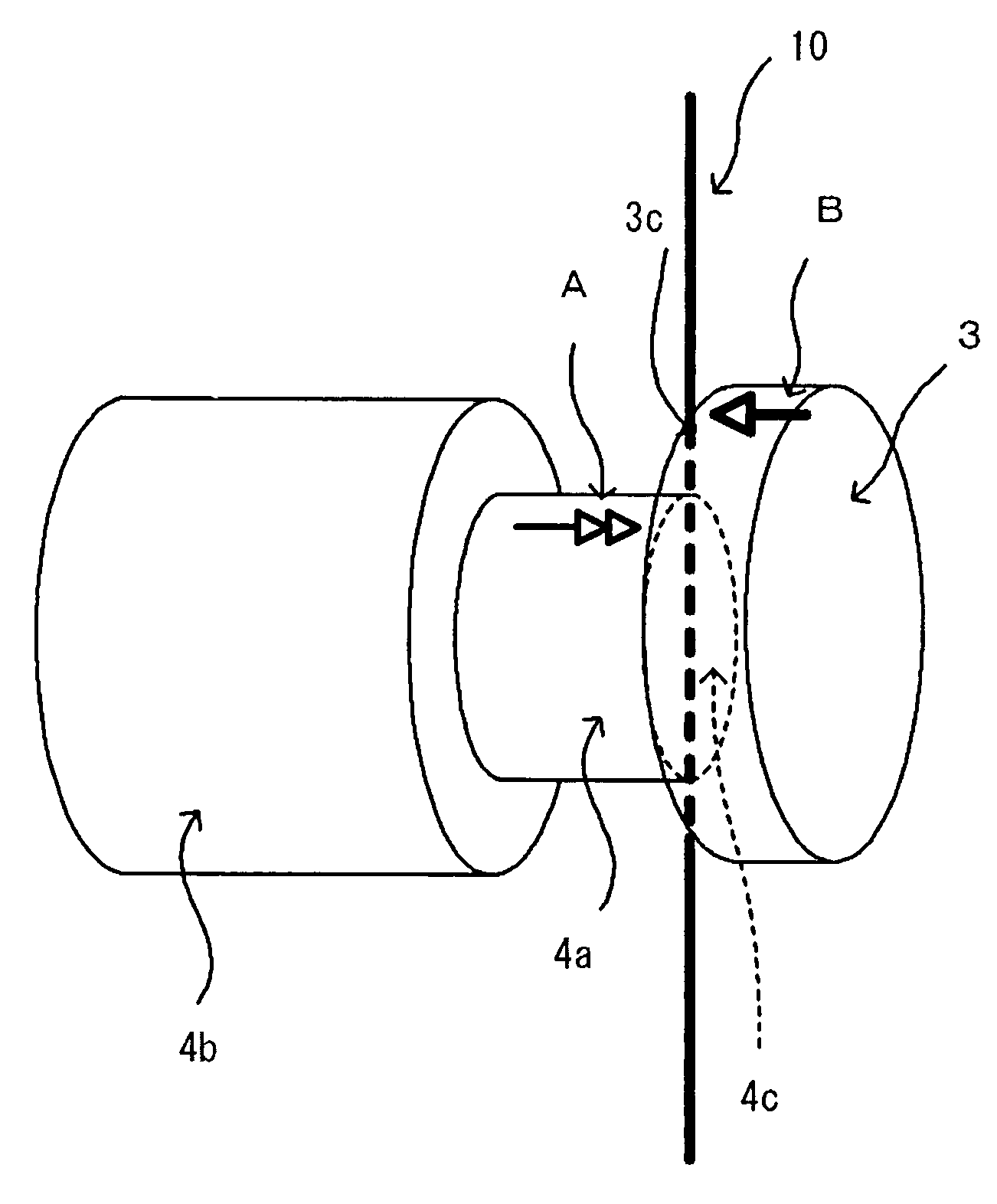
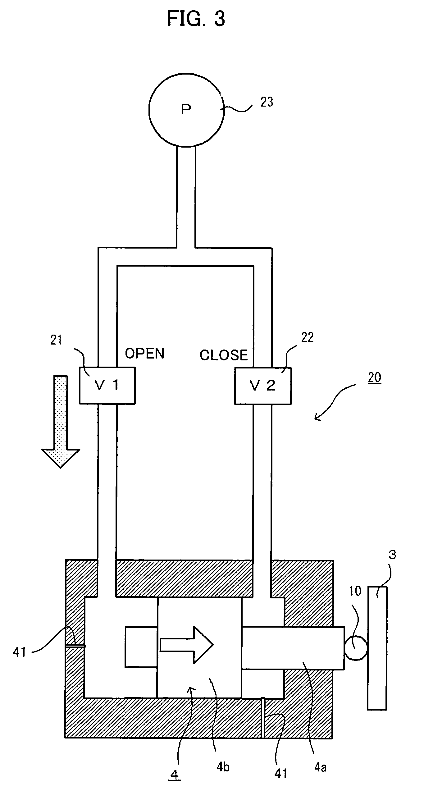
The present invention improves the contact between a wire electrode and a conducting member without deforming the wire electrode, reduces unnecessary loads on the wire-cut electric discharge machine, and makes an automatic wire connection easily. The wire-cut electric discharge machine includes a conducting member for supplying power to the wire electrode and a movable member that presses the wire electrode against the conducting member. The movable member automatically retracts from the wire electrode's path when the contact is too great, reducing the production of minute electric discharges. The movable member can be moved close to and apart from the conducting member to control the contact. The conducting member and the movable member hold the wire electrode in a straight line, reducing bending loads on the wire electrode. The movable member may be moved and held apart from the conducting member when a predetermined condition is fulfilled, reducing loads on the wire electrode and the wire-cut electric discharge machine.

Problems solved by technology

The structure in which the wire electrode is elastically held by the conducting members from either side as in JP59-134622A has the following problems: First, since the conducting members pressed are located in the traveling path of the wire electrode, it is difficult to carry out automatic connection of the wire electrode with certainty.
Further, in the structure in which the conducting members are pressed against the wire electrode by means of elastic devices such as springs, the contact pressure between the wire electrode and the conducting member cannot be changed.
If the contact pressure becomes lower, the wire electrode can break and the conducting member can wear with higher rate.
Hence, if the wire electrode oscillates with such a magnitude that the tensile force cannot keep the contact, the wire electrode gets out of contact with the conducting member and a space is produced between the wire electrode and the conducting member, which can cause minute electric discharges to be produced.
Further, the wire electrode is always subjected to a load which tends to bend the wire electrode.
Such deformation of the wire electrode produces a space between the wire electrode and the conducting member when the traveling is resumed, which can cause minute electric discharges to be produced.
As stated above, the structures proposed have problems such that the deformation of the wire electrode easily causes minute electric discharges to be produced, and that automatic wire connection cannot be carried out easily.
Hence, the structures proposed have a problem that various parts of the wire-cut electric discharge machine are subjected to loads.

Method used


Image

  • Wire-cut electric discharge machine
  • Wire-cut electric discharge machine
  • Wire-cut electric discharge machine

Examples


Embodiment Construction

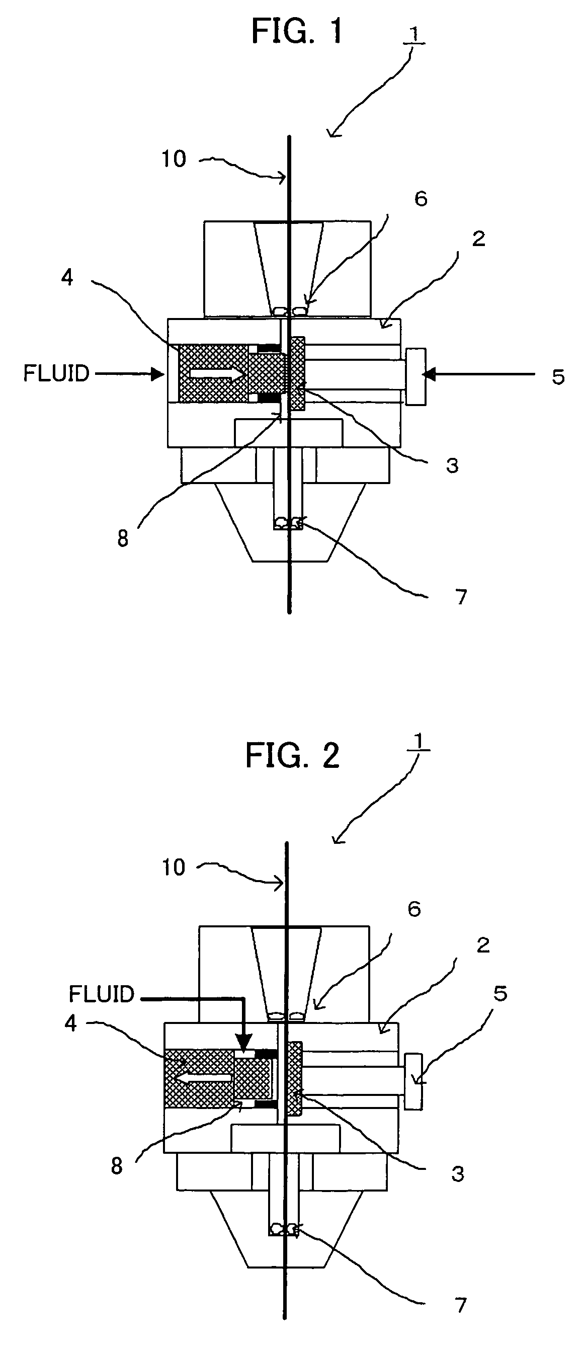
[0046]FIGS. 1 and 2 are cross-sectional views showing relevant parts of a wire-cut electric discharge machine according to this invention. FIG. 1 shows the state in which a movable member is pressing a wire electrode against a conducting member, and FIG. 2 shows the state in which a movable member has been retracted. It is to be noted that FIGS. 1 and 2 show only a head of a wire-cut electric discharge machine and its vicinity. Further, it is to be noted that the description of structural features which the wire-cut electric discharge machine normally has will be omitted.

[0047]In FIG. 1, a wire-cut discharge machine 1 has a head 2 having a vertically extending through-hole 8 through which a wire electrode 10 can travel, and a conducting member 3 which supplies electric power to the wire electrode 10 traveling through the through-hole 8. Over and under the head 2 are provided guides 6, 7 (sub-guide 6, dice guide 7), respectively, to guide the wire electrode 10 in traveling. While tra...


PUM

PropertyMeasurementUnit
electric poweraaaaaaaaaa
diameteraaaaaaaaaa
insulatingaaaaaaaaaa

Abstract

A wire-cut electric discharge machine which improves contact between a wire electrode and a conducting member without deforming the wire electrode to suppress production of minute electric discharges and reduce unnecessary loads on the wire electrode and the wire-cut electric discharge machine, and which makes it easy to make space on a wire traveling path to carry out automatic wire connection easily. In a wire-cut electric discharge machine having a conducting member for supplying an wire electrode with electric power for electric discharge machining, and making the wire electrode travel along a traveling path, sliding on the conducting member, a movable member capable of being moved nearer to and away from the conducting member is provided in a position opposite to the conducting member relative to the traveling path. By this arrangement, the contact between the wire electrode and the conducting member can be always kept without deforming the wire electrode.

Description

BACKGROUND OF THE INVENTION[0001]1. Field of the Invention[0002]The present invention relates to a wire-cut electric discharge machine which works on a workpiece using the energy of electric discharges produced between a wire electrode and the workpiece, and in particular, a mechanical part which supplies electric power to the wire electrode.[0003]2. Description of Related Art[0004]In the wire-cut electric discharge machine, as a way to supply electrical energy required for electric discharge machining to the wire electrode through a conducting member, it is known to bring the wire electrode into contact with the conducting member and make the wire electrode travel sliding on the conducting member.[0005]In the supply of electric power performed in the manner that the wire electrode travels sliding on the conducting member, the wire electrode gets in and out of contact with the conducting member as it oscillates. When the wire electrode gets out of contact with the conducting member,...

Claims


Application Information

Patent Timeline
Patent Type & Authority Patents(United States)
IPC IPC(8): B23H7/10
CPCB23H7/107
Inventor KITA, YUKITAKAYAMA, YUSHIMAKINO, YOSHINORI
Owner FANUC LTD
Learn More