Eureka AIR delivers breakthrough ideas for toughest innovation challenges, trusted by R&D personnel around the world.

Low drop-out voltage regulator with enhanced frequency compensation

a voltage regulator and frequency compensation technology, applied in the field of voltage regulators, can solve problems such as unstable output voltage, and achieve the effect of enhancing frequency compensation capacity

Inactive Publication Date: 2007-05-15
O2 MICRO INT LTD
View PDF11 Cites 17 Cited by
  • Summary
  • Abstract
  • Description
  • Claims
  • Application Information

AI Technical Summary

Benefits of technology

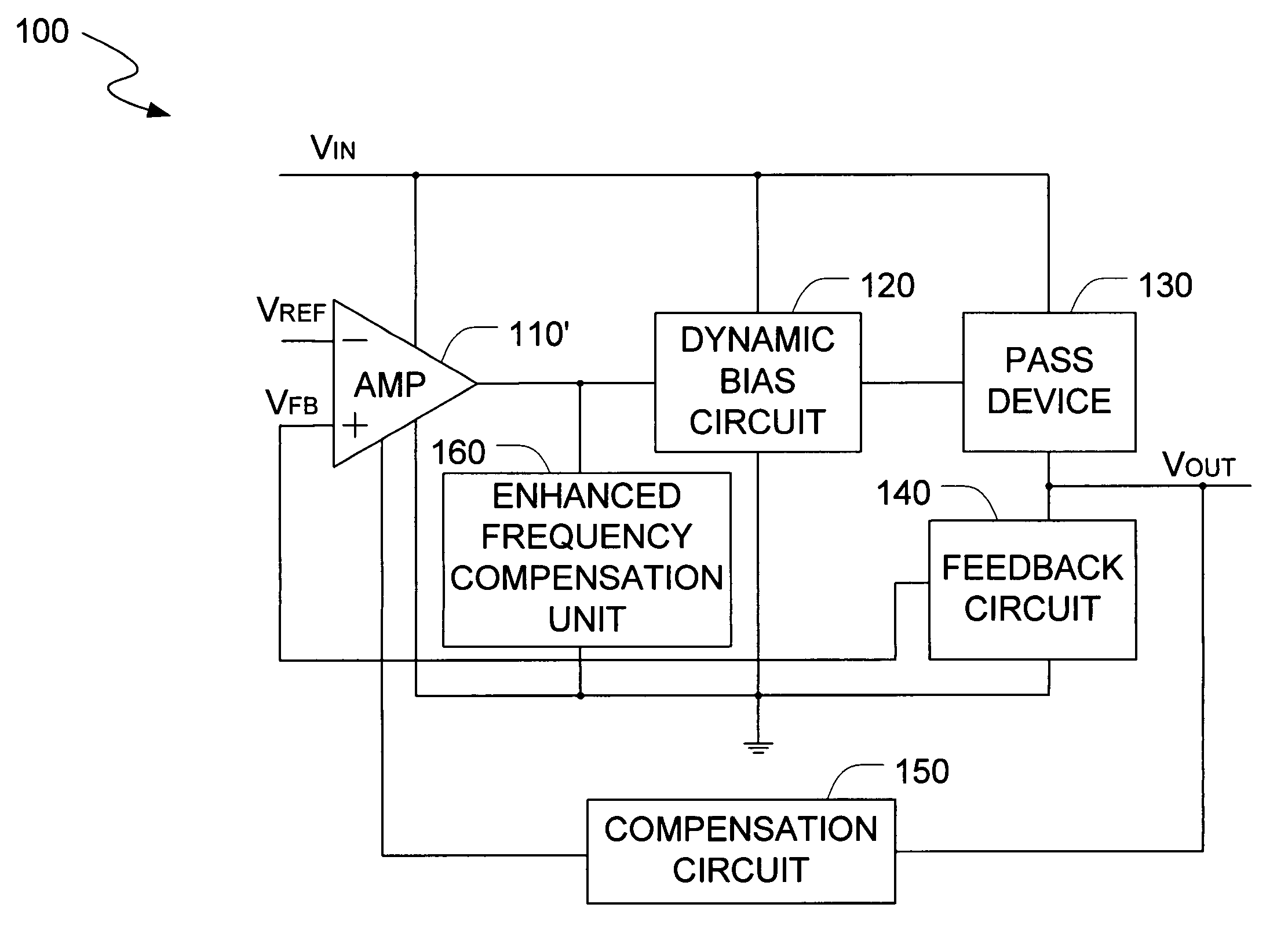
[0011]In yet another embodiment, the invention is a method for frequency compensation in a low drop-out voltage regulator circuit with enhanced frequency compensation capacity. This method includes the steps of generating an amplified voltage, receiving the amplified voltage at a dynamic bias circuit, generating a first output voltage at the dynamic bias circuit, driving a pass device with the first output voltage, increasing a slew rate for a gate voltage of the pass device through use of the dynamic bias circuit, receiving a second output voltage from the pass device, generating a zero reference value to stabilize the second output voltage, and regulating a damping factor to further stabilize the second output voltage.

Problems solved by technology

However, the Miller compensation capacitor may cause the two poles to meet together, and then generate two complex poles in a right-hand plane along a direction, especially when the LDO voltage regulator covers a larger range of a capacitive load with an equivalent serial resistance (ESR) and provides a large output current.
The right-hand plane poles can cause voltage oscillation at the LDO voltage regulators, which will make the output voltage unstable.

Method used


Image

  • Low drop-out voltage regulator with enhanced frequency compensation
  • Low drop-out voltage regulator with enhanced frequency compensation
  • Low drop-out voltage regulator with enhanced frequency compensation

Examples


Embodiment Construction

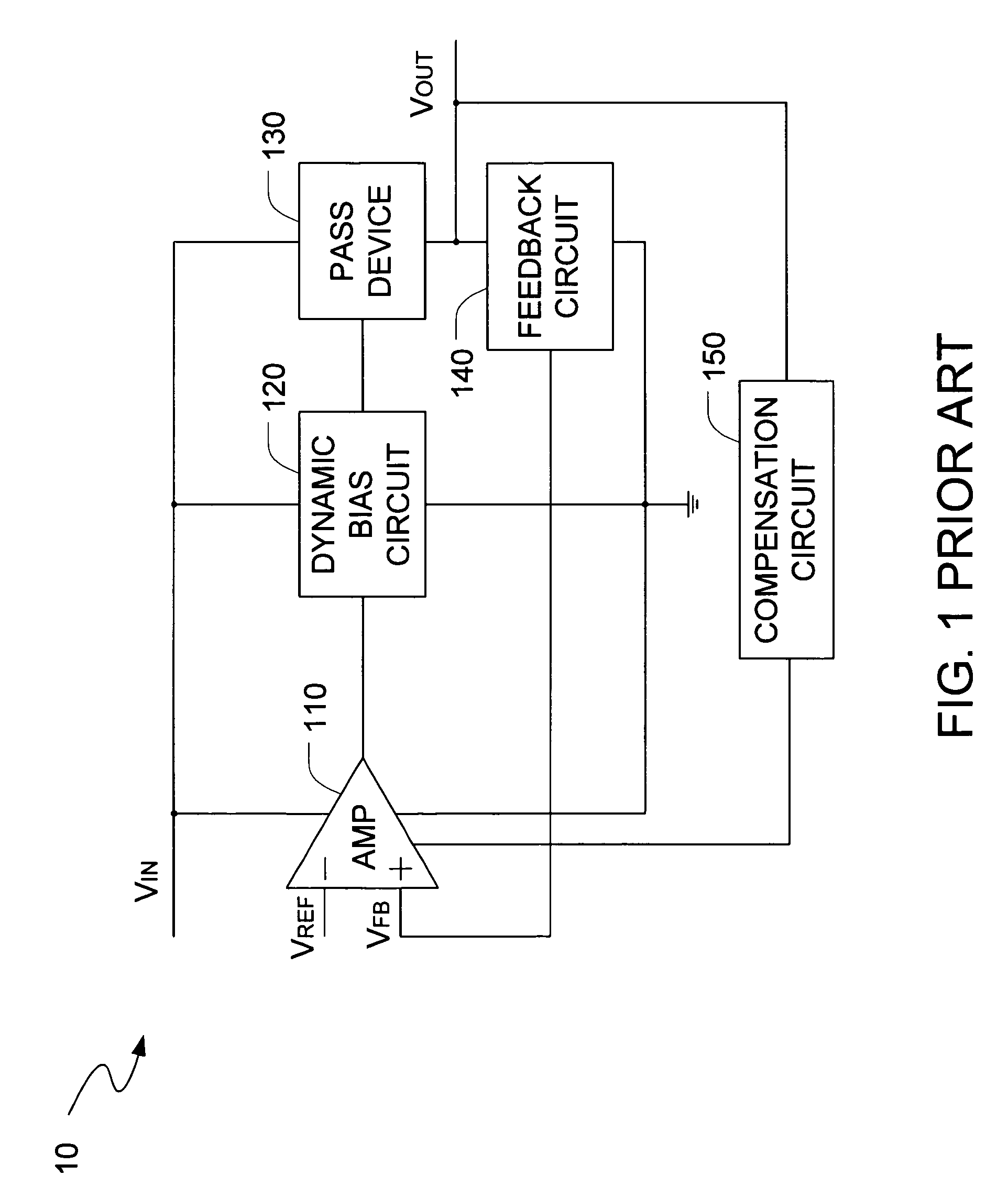
[0021]FIG. 1 illustrates a block diagram of a prior art LDO voltage regulator 10 with Miller compensation. Traditionally, the voltage regulator 10 includes an error amplifier 110, a pass device 130, a feedback circuit 140, and a compensation circuit 150. The voltage regulator 10 can further include a dynamic bias circuit 120 to increase the response speed of the LDO structure through enlarging the slew rate for a gate voltage of a MOS transistor incorporated in the pass device 130. A power supply voltage VIN is provided to the error amplifier 110, the dynamic bias circuit 120, and the pass device 130, respectively. The pass device 130 can provide an output voltage VOUT at an output terminal to an external load (not shown).

[0022]The error amplifier 110 can amplify a differential value between two input signals and then output the amplified value at its output terminal. A first signal, for example, a predetermined reference voltage VREF is provided to an inverting input terminal of th...


PUM


Abstract

The present invention is a voltage regulator circuit with enhanced frequency compensation. The voltage regulator includes an error amplifier, a dynamic bias circuit, an enhanced frequency compensation unit, a pass device and a compensation circuit. A signal from the pass device acts as an input signal of the error amplifier and is compared with another input signal, producing a differential signal. The differential signal is amplified and then provided to the dynamic circuit and the enhanced frequency compensation unit. The enhanced frequency compensation unit is provided such that a zero reference value in a left-hand plane can be generated to optimize the compensation for the voltage regulator circuit. The error amplifier includes a capacitor for compensating an output voltage of the voltage regulator circuit.

Description

RELATED APPLICATION[0001]This application claims the benefit of U.S. provisional application, titled Enhanced Compensation Strategy for Low Quiescent Current, Low Drop-out Voltage Regulator, Ser. No. 60 / 656,732, filed on Feb. 25, 2005, the specification of which is incorporated herein in its entirety by this reference.BACKGROUND OF THE INVENTION[0002]1. Field of the Invention[0003]The present invention relates to voltage regulators and in particular, to a low drop-out voltage regulator with low power dissipation.[0004]2. Description of the Related Art[0005]Currently, the increasing demand for higher performance power supply circuits has resulted in a continued development of voltage regulator devices. Many low voltage applications, such as for use in cell phones, pagers, laptops, camera recorders and other mobile battery operated devices, require the use of low drop-out (LDO) voltage regulators. These portable electronics applications typically require low voltage and small quiescen...

Claims


Application Information

Patent Timeline
Patent Type & Authority Patents(United States)
IPC IPC(8): G05F1/00
CPCG05F1/575
Inventor WANG, WEITANG, XIAOHUHOU, XIAOHUA
Owner O2 MICRO INT LTD
Why Eureka
Eureka Blog
Learn More