Method for deciding tilt angle of antenna in radio communication system and apparatus for deciding the same

a radio communication system and antenna technology, applied in the field of radio communication systems, can solve the problems of inconsistent increased deterioration rate due to an increase in tilt angle, and large increase in so as to achieve reduce the effect of deterioration rate and small deterioration rate of the entire system

Inactive Publication Date: 2007-05-15
NEC CORP
View PDF9 Cites 7 Cited by
  • Summary
  • Abstract
  • Description
  • Claims
  • Application Information

AI Technical Summary

Benefits of technology

[0028]The present invention has been accomplished in the light of the foregoing problems of the conventional techniques, and an object thereof is to provide a method for deciding tilt angles which enable a sufficiently small deterioration rate of the entire radio communication system. Another object of the present invention is to provide a method for deciding tilt angles, which makes it possible to obtain consistent tilt angles that realize a sufficiently small deterioration rate of the entire radio communication system in the same radio communication system without regard to the operator.
[0038]Furthermore, where a tilt angle of an antenna is decided and then a different antenna is selected to set its tilt angle, an antenna at a certain tilt angle interferes with its neighboring area, affecting optimum tilt angles of other antennas in a radio communication system. Even in such a radio communication system, the present invention enables tilt angles of respective antennas to realize a sufficiently small deterioration rate of the entire system.
[0039]The first advantageous effect of the present invention is that one can obtain tilt angles which enable a small deterioration rate of the entire system compared with that obtained from initial values of tilt angles.
[0040]The second advantageous effect is that, by automating the way to decide tilt angles, any operator can obtain the same result of optimal tilt angles regardless of operator's experience if initial setting is the same.
[0041]The third advantageous effect is that one can decide tilt angles more quickly and more accurately.

Problems solved by technology

As a result, the deterioration rate of the antenna tends to increase.
However, in coverage with a sufficiently small deterioration rate, an increase in deterioration rate due to an increase in tilt angle is often very small.
However, the results vary depending on experience of the person in charge, and a deterioration rate of the entire system therefore becomes inconsistent.
Accordingly, a stable quality cannot be maintained.
Moreover, selecting antennas from many of them and deciding their angles have been time-consuming operations.
It has been very difficult to obtain tilt angles which enable sufficiently small deterioration rate of the entire system within a limited period of time particularly in a large radio communication system where an enormous number of antennas are located.
Moreover, where an antenna with a certain tilt angle interferes with a neighboring area, affecting optimal tilt angles of other antennas, in other words, in the case of a radio communication system where antennas are affecting each other (for example, CDMA (Code Division Multiple Access)), optimization of tilt angles has been even more difficult.
Further, adjustment of an antenna does not always affect the neighboring area only, making the optimization even more difficult.
Therefore, it has been very difficult to obtain tilt angles which enable a sufficiently small deterioration rate of the entire system.

Method used


Image

  • Method for deciding tilt angle of antenna in radio communication system and apparatus for deciding the same
  • Method for deciding tilt angle of antenna in radio communication system and apparatus for deciding the same
  • Method for deciding tilt angle of antenna in radio communication system and apparatus for deciding the same

Examples


first embodiment

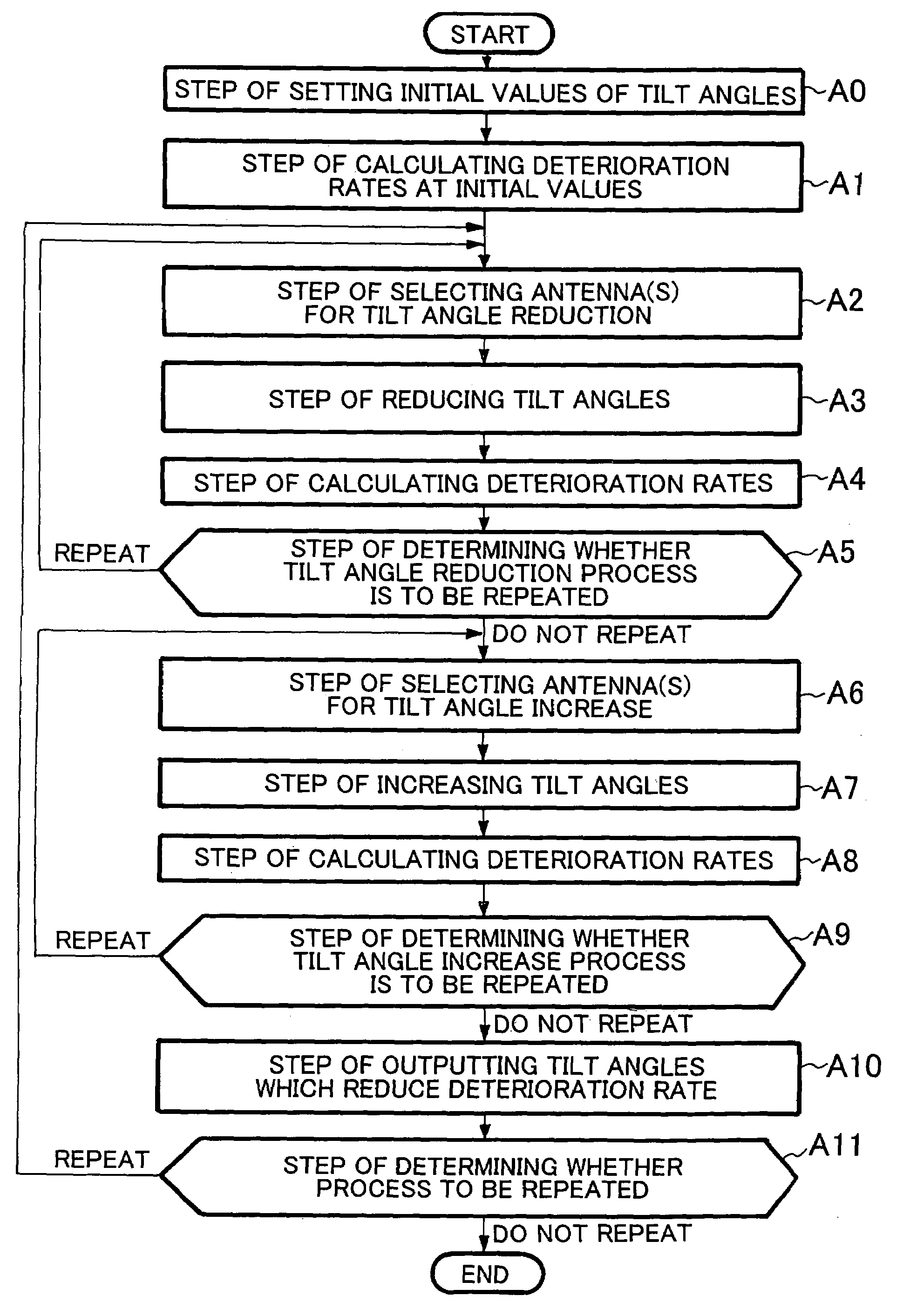
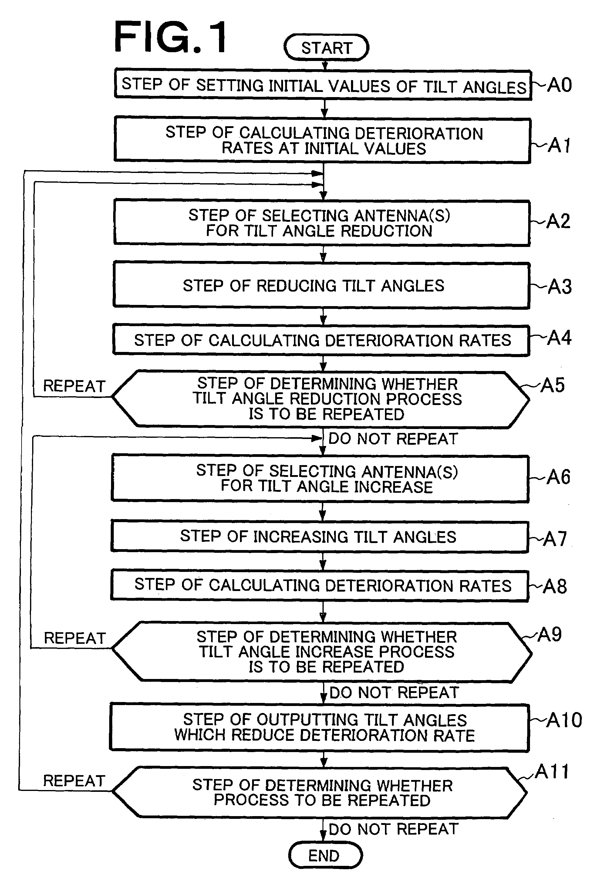
[0048]FIG. 1 is a flowchart showing a process of a method for deciding tilt angles carried out in the present invention. This embodiment is a process carried out for deciding tilt angles of antennas in a radio communication system, like a CDMA cellular system, which includes a plurality of radio base stations, each having an antenna with directivity in a vertical plane.

[0049]A deterioration rate of each antenna is calculated by a simulator having a simulation function.

[0050]The process according to the present embodiment includes steps A0 to A11 described below.

[0051]The process includes a step of setting initial values of tilt angles (Step A0), a step of calculating a deterioration rates at the initial values of tilt angles (step A1), a step of selecting antenna(s) for tilt angle reduction based on a predetermined evaluation index (Step A2), a step of reducing tilt angles of the selected antenna(s) (Step A3), a step of calculating a deterioration rates when tilt angles are reduced ...

second embodiment

[0108]Next, the present invention is described in detail with reference to the drawings.

[0109]FIG. 3 is a flowchart showing the operations of the second embodiment of the present invention. In the present embodiment, a step of setting a parameter for tilt angle reduction (Step A12) in accordance with an accumulated number of repetitions of the entire process is added between Steps A1 and A2 in the flowchart of FIG. 1 showing the operations of the first embodiment, and a step of setting a parameter for tilt angle increase (Step A13) in accordance with an accumulated number of repetitions of the entire process is added between Steps A5 and A6 of the same.

[0110]As stated below, the step of setting a parameter for tilt angle reduction (Step A12) sets a parameter for tilt angle changes used in the step for reducing tilt angles (Step A3) in accordance with the number of times that “the entire repeated processes,” i.e. the series of Steps A12, A2, A3, A4, A5, A13, A6, A7, A8, A9, A10 and ...


PUM


Abstract

The purpose of the present invention is to provide a tilt angle deciding method and a system wherein tilt angles to diminish the deterioration rate of the entire system can be obtained in the radio communication system. The method comprises the steps of setting initial values of tilt angles; calculating the deterioration rate at the initial values of tilt angles; selecting an antenna for reducing a tilt angle; reducing the tilt angle of the selected antenna; calculating a deterioration rate at the time when the tilt angle is reduced; determining the continuity of repeating the processes, after repeating the series of processes for reducing these tilt angles, and increasing tilt angles repeatedly in the similar way. In addition, the method comprises the steps of outputting tilt angles for diminishing a small deterioration rate, and determining whether the processes of repeating the whole steps finish. With the above-specified processes, it becomes possible to obtain tilt angles for diminishing the deterioration rate of the entire system in comparison with that obtained at initial values of tilt angles.

Description

CROSS-REFERENCE TO RELATED APPLICATIONS[0001]This application is a national stage application under 35 U.S.C. § 371 and claims priority under 35 USC § 365(c) of International Application PCT / JP2003 / 011152, filed on Aug. 4, 2004, which designated the United States, was published in Japanese, and which in turn claims priority to Japanese Patent Application JP2003-285731, filed on Aug. 4, 2003. The entirety of each of which is incorporated herein by reference.BACKGROUND OF THE INVENTION[0002]1. Field of the Invention[0003]The present invention relates to a radio communication system including a plurality of base stations and particularly to a method for deciding tilt angles used in deciding a tilt angle of an antenna located in each base station to reduce a deterioration rate of the entire radio communication system, and to an apparatus for deciding the same.[0004]2. Description of the Related Art[0005]Concerning a radio communication system including a plurality of base stations that ...

Claims


Application Information

Patent Timeline
Patent Type & Authority Patents(United States)
IPC IPC(8): H04M1/00G01S19/23H01Q1/12H01Q1/24H01Q3/26H04W16/28
CPCH01Q1/125H01Q1/246
Inventor AOYAMA, AKIOHAMABE, KOJIRO
Owner NEC CORP
Why Eureka
Try Eureka