Clip and airbag body installation structure

a technology for installing structures and airbags, which is applied in the direction of threaded fasteners, screwdrivers, pedestrian/occupant safety arrangements, etc., can solve the problems of difficult to increase the length of inserts, and achieve the effect of easy and stably installing the airbag body in the body panel, and easy and stably installing the airbag body

Inactive Publication Date: 2007-05-22
NIFCO INC
View PDF7 Cites 12 Cited by
  • Summary
  • Abstract
  • Description
  • Claims
  • Application Information

AI Technical Summary

Benefits of technology

[0010]In the invention, the male member and female member are integrated with the connecting piece, so that the clip is easily handled in a production line. The male member is supported on the female member via the connecting piece while the lower end of the shaft leg is positioned directly above the upper cylinder end of the female member. Accordingly, from a temporarily fixed state wherein the female member is inserted into the installation hole to engage the edge of the hole, it is possible to simply push the head of the male member straight without positioning the male member, so that the male member is properly pushed into the female member. Therefore, it is possible to permanently attach the female member to the installation hole with a single motion.
[0011]When the male member is pushed into the female member, the connecting piece is bent and sandwiched between the head of the male member and the outer flange of the female member in a folded state. At this time, the connecting piece is bent with the mid section thereof as the bending center and the side thereof on the other side of the axis line of the leg shaft of the male member as the outside of the bending. Accordingly, the connecting piece does not extend outwardly beyond an outer edge of the head of the male member. Therefore, when the clip is fully fixed, it is not necessary to provide a space beyond a size of the head of the male member at a location where the clip is installed. As a result, it is possible to increase a length of the connecting piece or the leg shaft of the male member supported by the connecting piece.
[0012]According to the present invention, the connecting pieces may be disposed on both sides of the axis shaft of the male member. In this case, it is possible to stably support the male member above the outer flange of the female member.
[0013]According to the present invention, the head of the male member and the outer flange of the female member may be formed in substantially square shapes, respectively. One of a pair of connecting pieces has an upper end connected to one corner of the head of the male member, and a lower end connected to one corner of the outer flange of the female member located directly below the one corner of the head. The other of the pair of connecting pieces has an upper end connected to another corner of the head of the male member diagonally opposite to the one corner, and a lower end connected to another corner of the outer flange of the female member diagonally opposite to the one corner. In this case, it is possible to stably support the male member above the outer flange of the female member.
[0015]According to the present invention, an airbag body installation structure or configuration includes an installation plate attached to an airbag body of an airbag device and having an installation hole, and the clip described above. After the installation hole of the installation plate is aligned with an installation hole formed in an automotive body panel, the female member is inserted into the installation holes, and the leg shaft of the male member is pushed into the female member to install the airbag body to the body panel. Accordingly, it is possible to easily and stably install the airbag body in the body panel.
[0016]In the clip of the present invention, even when the male member has a relatively long leg shaft, thereby making the connecting piece relatively long, the connecting piece does not extend outwardly greatly. In the airbag body installation configuration of the present invention, it is possible to easily and stably install the airbag body in the body panel. It is also possible to attach the clip with a limited space for the head of the male member around the installation hole of the installation plate.

Problems solved by technology

In this case, when the connecting piece is bent, the connecting piece outwardly extends greatly, thereby making it difficult to increase a length of the insert.

Method used


Image

  • Clip and airbag body installation structure
  • Clip and airbag body installation structure
  • Clip and airbag body installation structure

Examples


Embodiment Construction

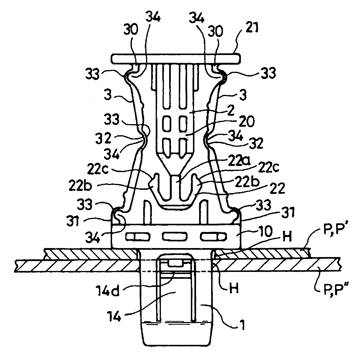
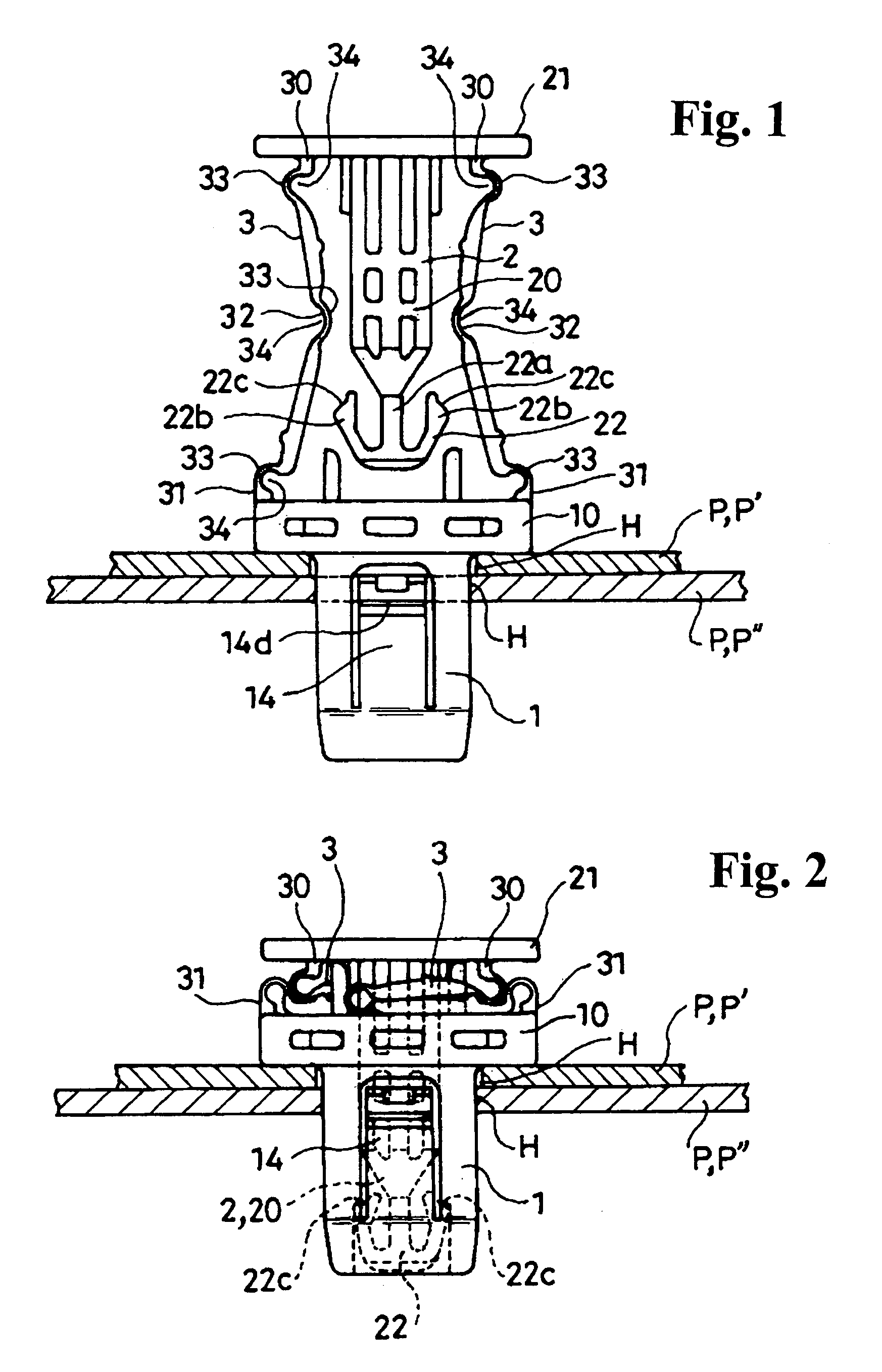
[0026]Hereunder, embodiments of the present invention will be explained with reference to the accompanying drawings. FIGS. 1 and 2 show a clip according to an embodiment of the present invention in temporarily and fully fixed states, respectively.

[0027]The clip comprises a female member 1 inserted into an installation hole H formed in a panel P to be temporarily fixed thereto, and a male member 2 to be pushed into the female member 1 to change the temporarily fixed state of the female member 1 into a fully fixed state. The clip is typically inserted into installation holes H formed in two or more panels P after overlaying the two or more panels P to align the holes, so that the two or more panels P are fastened together via the clip.

[0028]In an installation configuration of an airbag body (referred generally to as a bag normally stored in a folded state and deployed by gas discharged from a gas discharging device using an impact of a vehicular collision as a trigger), an installatio...


PUM


Abstract

A clip includes a female member, a male member, and a connecting piece. The female member is formed in a cylindrical shape with two open ends, and has an outer flange at an upper cylinder end. A flexible engaging piece is formed in a side section defined by slits formed in the side section, and is provided with an engaging surface facing the outer flange. The male member is formed of a leg shaft and a head provided at an upper end of the leg shaft for a pushing operation. The connecting piece connects the head of the male member with the outer flange of the female member, so that a lower end of the leg shaft of the male member is positioned directly above the upper cylinder end of the female member.

Description

BACKGROUND OF THE INVENTION AND RELATED ART STATEMENT[0001]The present invention relates to a clip comprising a female member to be inserted into an installation hole formed in a panel in a temporarily fixed state, and a male member to be pushed into the temporarily fixed female member to change the temporarily fixed state into a secure and fully fixed state. The present invention also relates to an airbag installation structure that includes the clip.[0002]Patent Reference 1 has disclosed a clip formed of an insert to be inserted into a through hole of a member, and a flange having an opening for inserting the insert and connected to the insert with a bendable connecting piece. In the clip, the insert is pushed into the through hole via the opening of the flange while bending the connecting piece, so that the clip is fixed to the member.[0003]When the insert is inserted into the through hole, the connecting piece is bent such that a bending center moves away from an axis of the ins...

Claims


Application Information

Patent Timeline
Patent Type & Authority Patents(United States)
IPC IPC(8): F16B5/06F16B19/00B60R21/20E04F19/02F16B19/10F16B21/08
CPCF16B5/0642B60R21/20Y10T24/42Y10T24/309F16B21/086H01H13/70H01H13/83H01H2219/014H05B33/04
Inventor TASHIMA, TAKUITO, KAZUO
Owner NIFCO INC
Why Eureka
Try Eureka