
Method for determining and correcting for turbine meter overspin at the instantaneous stoppage of flow rate

a technology of turbine meter and flow rate, which is applied in the field of turbine meter overspin correction, can solve the problems of inability to control the process of the metering system, the inability of the flow switch to be added, and the cost of the flow switch to solve the problem, etc., and achieve the effect of improving accuracy

Active Publication Date: 2007-05-22
OLIVIER PAUL D
View PDF3 Cites 5 Cited by
  • Summary
  • Abstract
  • Description
  • Claims
  • Application Information

AI Technical Summary

Benefits of technology

The technical effect of this patent is that it describes a new type of turbine meter system that can measure things more accurately than existing methods.

Problems solved by technology

The technical problem addressed in this patent text is finding ways to accurately measure the flow rate of liquids caused by sudden changes in the direction of flow or starting/stopping of the control valve, without incurring errors due to overspan. Previous methods like instrumenting the valve or adding a flow switch come with their own limitations including increased costs and reduced accuracy.

Method used


Image

  • Method for determining and correcting for turbine meter overspin at the instantaneous stoppage of flow rate
  • Method for determining and correcting for turbine meter overspin at the instantaneous stoppage of flow rate
  • Method for determining and correcting for turbine meter overspin at the instantaneous stoppage of flow rate

Examples


Embodiment Construction

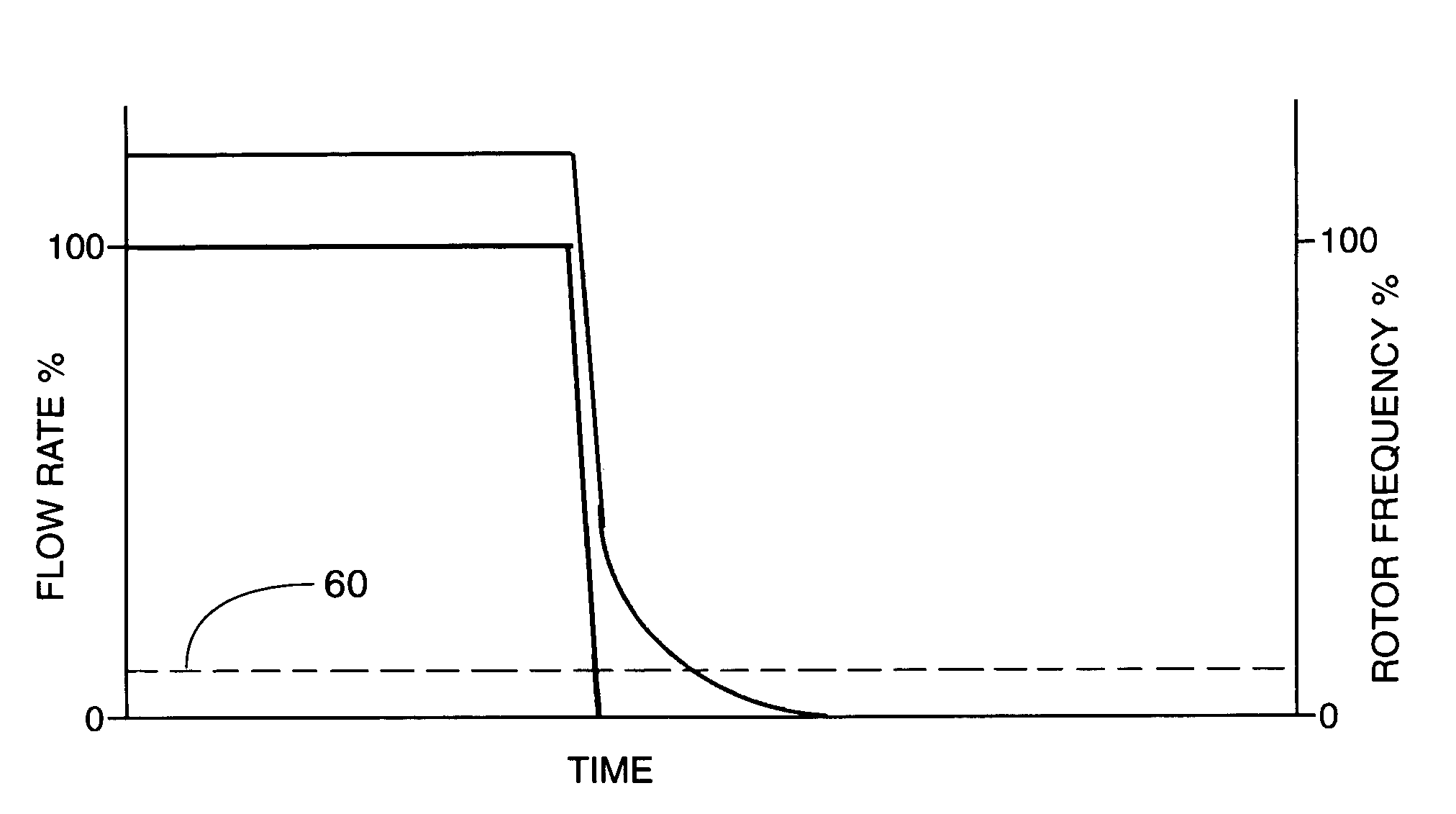
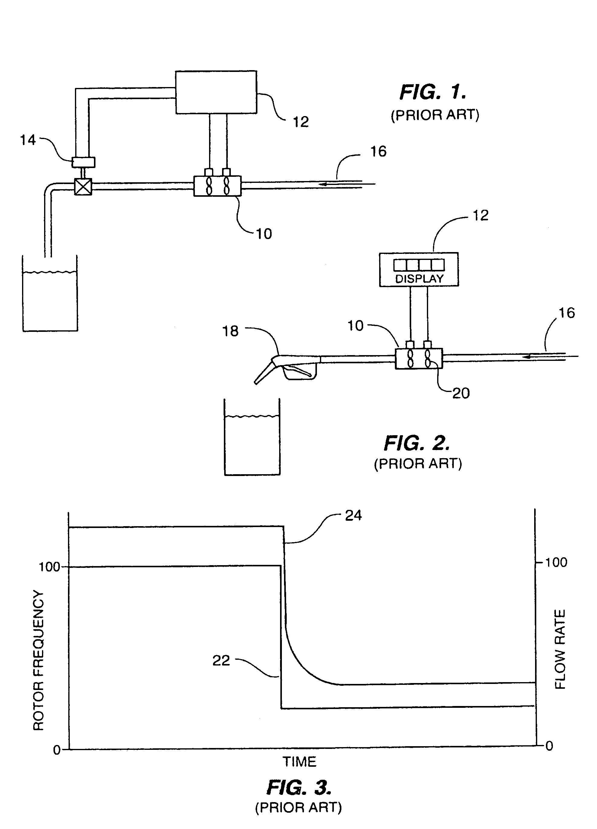
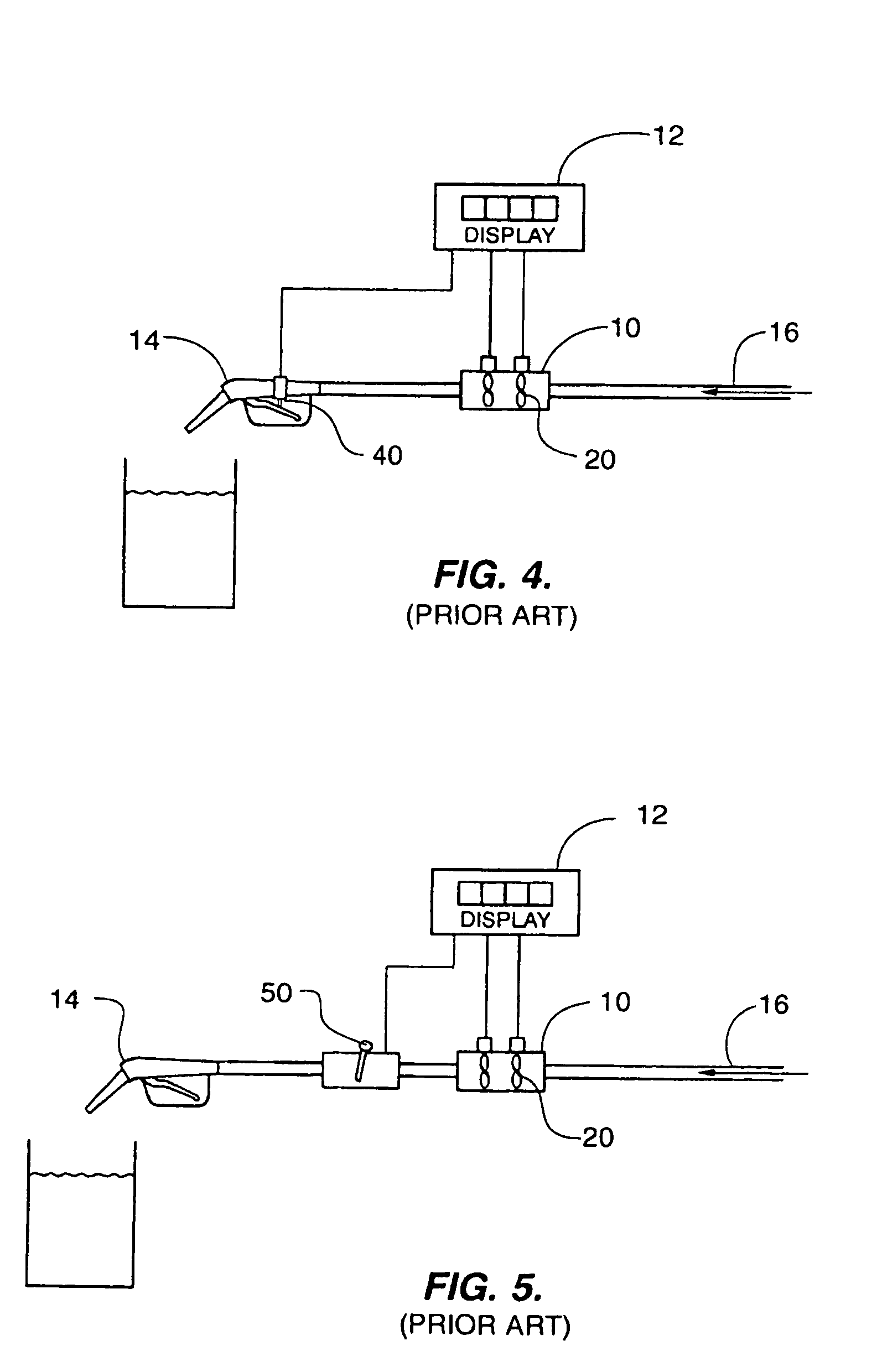
[0026]A software solution within an existing turbine meter microprocessor 12 that is capable of detecting the difference between a partial closure of control valve 14 and a full closure of control valve 14 is an ideal solution to the problem. Microprocessor 12 is capable of detecting a rapid deceleration (decreasing change of rotor frequency) of the rotor(s). Typical microprocessor 12 speeds and rotor blade passing frequencies 24 are sufficient to detect the occurrence of a rapid deceleration within 1–2 milliseconds and compute the rate of deceleration within another 1 microsecond.

[0027]Once the rapid deceleration is detected, one of two future conditions will occur. A lower steady state flow rate 22 will stabilize within a fraction of a second, which is a valid condition, or the flow rate 22 has been stopped and turbine rotors 20 are continuing to spin (over spin) when no flow is present, which is an invalid condition.

[0028]When microprocessor 12 detects the rapid deceleration, sai...


PUM


Abstract

A method of correcting for overspin in a turbine meter is provided. The turbine meter has turbine rotors positioned in a pipe in which liquid passes therethrough. The turbine rotors rotate in response to movement of the liquid passing through the pipe and sensors mounted proximate thereto count each passage of a rotor by providing an electronic pulse to a microprocessor. The microprocessor calculates the frequency of the electronic pulses which is directly proportional to the total quantity of liquid passing therethrough. If the microprocessor detects a rapid decrease in the frequency of the electronic pulses from the one or more sensors, it begins storing the frequency data therein. The microprocessor determines whether the decrease is due to a total shut off of liquid flowing or to a slow down of said flow. If a slowdown, the stored frequencies are used to compute the total quantity flowing through said pipe. If a shut down, the stored frequencies are deleted and not used to calculate total frequency.

Description


Claims


Application Information

Patent Timeline
Owner OLIVIER PAUL D
Learn More