Grate plate arrangement for step plates

a technology of step plate and grate plate, which is applied in the directions of furniture, transportation and packaging, lighting and heating equipment, etc., can solve the problem of unnecessary use of studs made of high-temperature materials

Inactive Publication Date: 2007-05-22
IKN GMBH
View PDF27 Cites 6 Cited by
  • Summary
  • Abstract
  • Description
  • Claims
  • Application Information

AI Technical Summary

Benefits of technology

[0007]The task of this invention is to create a grate plate arrangement for step grates where the studs are protected from direct contact with the granulated materials and hence from strong wear and tear and thermal stress. According to the invention, this task is accomplished by covering the bolt heads of the studs by a cover.
[0008]Covering the bolt heads prevents the studs from being directly exposed to the effects of heat through the granulated materials, making the use of studs made of high-temperature material unnecessary. Moreover, the bolt heads are protected against the abrasive effect of the granulated materials and hence from wear and tear, making them easily detachable by normal means using a wrench if and when the front plate has to be readjusted. Another advantage is that the studs can be reused.

Problems solved by technology

Covering the bolt heads prevents the studs from being directly exposed to the effects of heat through the granulated materials, making the use of studs made of high-temperature material unnecessary.

Method used


Image

  • Grate plate arrangement for step plates
  • Grate plate arrangement for step plates
  • Grate plate arrangement for step plates

Examples


Embodiment Construction

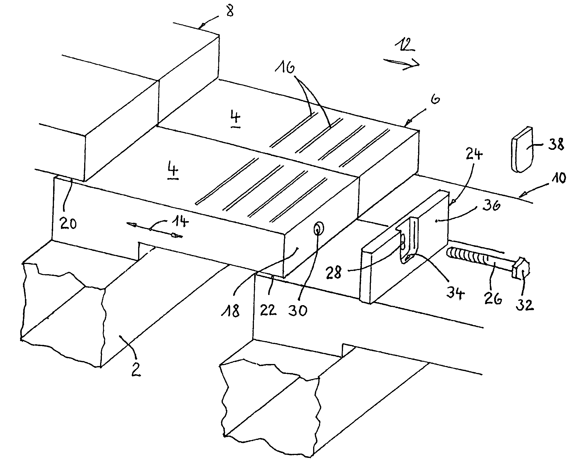
[0033]The basic setup of a step grate, to which the present invention relates, is shown in FIG. 1. Several grate plates 4 laid out beside each other on a grate carrier 2 form a grate plate row 6. Several grate plate rows 8, 6, 10 laid out one after the other form the grate, which as such, is already generally known and therefore not described here in more detail. The grate plate rows 8, 6, 10 laid out one after the other each have a stepped overlapping arrangement so that the front area of the grate plates of one grate plate row is resting on the rear area of the grate plates of the grate plate row following in the conveying direction 12. In the example of FIG. 1, grate plate row 6 is movable back and forth in the direction of double arrow 14, while grate plate rows 8 and 10 are stationary grate plate rows. Other arrangements where several movable grate plate rows alternate with several immovable ones are possible.

[0034]The granulated materials resting on the grate are cooled by the...


PUM


Abstract

A grate plate arrangement for step grates includes box-like grate plates (4) positioned on a grate carrier (2) with a front plate (24) placed on its end wall (18) and fastened to the end wall (18) using one or more studs (26) screwed to the grate plate (4). The bolt head (32) of each stud (26) is countersunk into a recess (34) built into the front plate (24) and covered on the outside by covering (cover 38) and secured against unscrewing.

Description

CROSS REFERENCES TO RELATED APPLICATIONS[0001]This application claims the priority benefit of German Patent Application No. 10 2004 040 048.2 filed on Aug. 18, 2004.STATEMENT REGARDING FEDERALLY SPONSORED RESEARCH[0002]Not Applicable.DESCRIPTION OF THE BACKGROUND ART[0003]This invention relates to a grate plate arrangement for step grates. Generally, step grates include several grate plates laid out beside each other on one grate carrier to form one grate plate row; several grate plate rows laid out behind each other in the conveying direction form the step grate. The grate plate rows have a stepped arrangement, that is, the front area of each grate plate row rests on the rear area of a following grate plate row in the conveying direction. To convey granulated materials lying on the grate, in general individual grate plate rows are arranged movable in the conveying direction while other grate plate rows remain immovable.[0004]Special problem areas of this type of step grates are the...

Claims


Application Information

Patent Timeline
Patent Type & Authority Patents(United States)
IPC IPC(8): F23H3/00
CPCF23H7/08F23H17/00F27D15/0213
Inventor VON WEDEL, KARL
Owner IKN GMBH
Why Eureka
Try Eureka