Disc brake for vehicle

a disc brake and disc rotor technology, applied in the direction of braking elements, slack adjusters, braking members, etc., can solve the problems of friction pads being pushed away from the disc rotor, unable to prevent the ears from playing in the disc radial direction inside the pad guide groove, and the attachment work is long, so as to increase the ease of attachment and prevent friction pads from falling

Active Publication Date: 2007-05-22
HITACHI ASTEMO LTD
View PDF8 Cites 42 Cited by
  • Summary
  • Abstract
  • Description
  • Claims
  • Application Information

AI Technical Summary

Benefits of technology

[0007]An object of the present invention is therefore to provide a disc brake for a vehicle capable of preventing friction pads from falling off a caliper bracket in tentatively attaching the friction pads to caliper support arms of the caliper bracket and thereby increasing the ease of attachment.
[0008]An another object of the present invention is therefore to provide a disc brake for a vehicle in which pad springing-back portions are solely able to not only return friction pads but also effectively prevent play of ears to thereby reduce brake noise and suppress juddering caused by wear of a disc rotor and effectively prevent generation of a friction pad striking sound due to play of the ears and further the pad springing-back portions are solely able to prevent the friction pads from falling off a caliper bracket in attaching the friction pads to the caliper bracket tentatively to thereby allow the friction pads to be attached easily.

Problems solved by technology

However, with the above configuration in which the pad returning mechanisms urge the friction pads away from the disc rotor, in tentatively attaching the friction pads to the pad guide grooves of the caliper support arms, the friction pads are pushed away from the disc rotor and may fall off the caliper support arms.
As a result, the attachment work takes much time.
Although as described above the pad retainers having the above structure have the effect of returning the friction pads from the disc rotor in a non-braking state, they cannot prevent the ears from playing in the disc radial direction inside the pad guide grooves.
Further, since the friction pads are always urged away from the disc rotor by the pad springing-back portions, the friction pads are prone to fall off a caliper bracket in attaching the friction pads to the caliper bracket tentatively.
The attachment work thus takes much time.

Method used


Image

  • Disc brake for vehicle
  • Disc brake for vehicle
  • Disc brake for vehicle

Examples


first embodiment

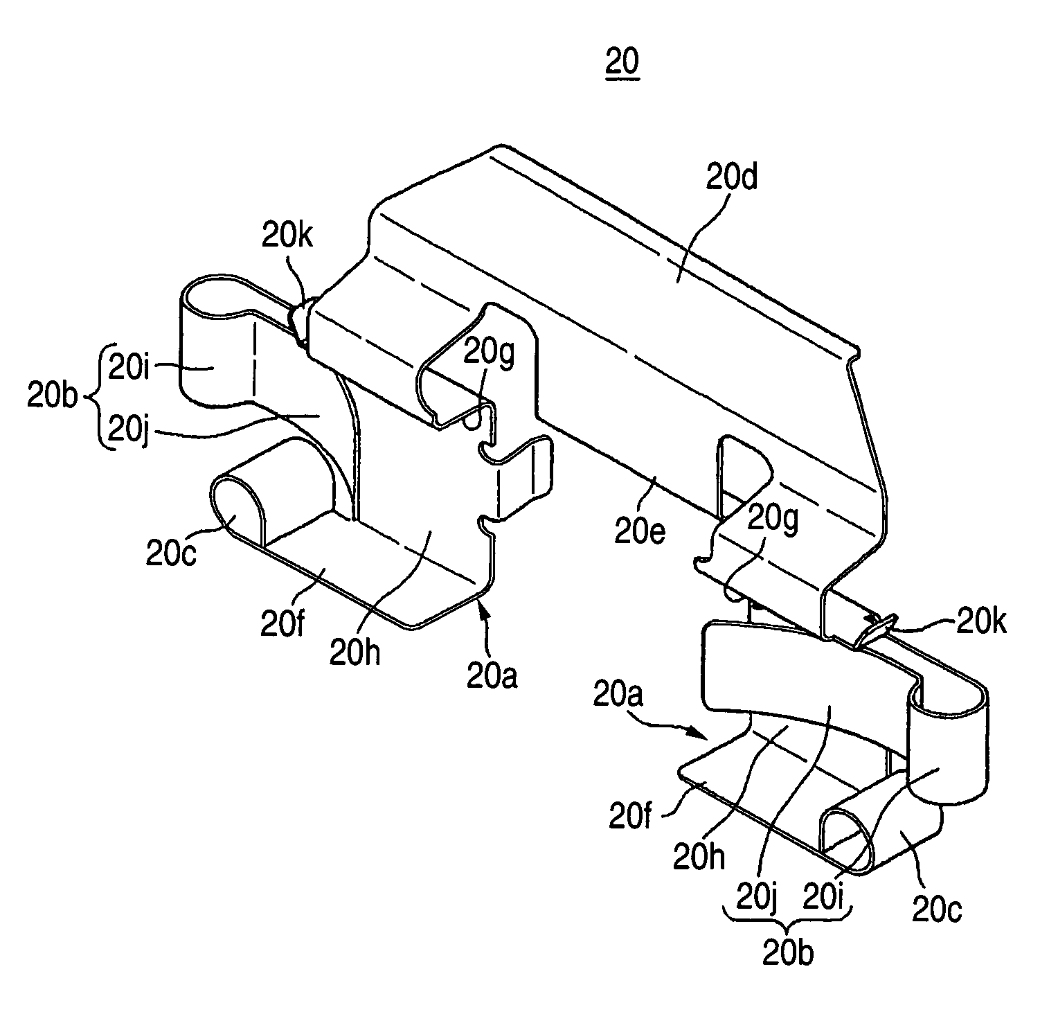
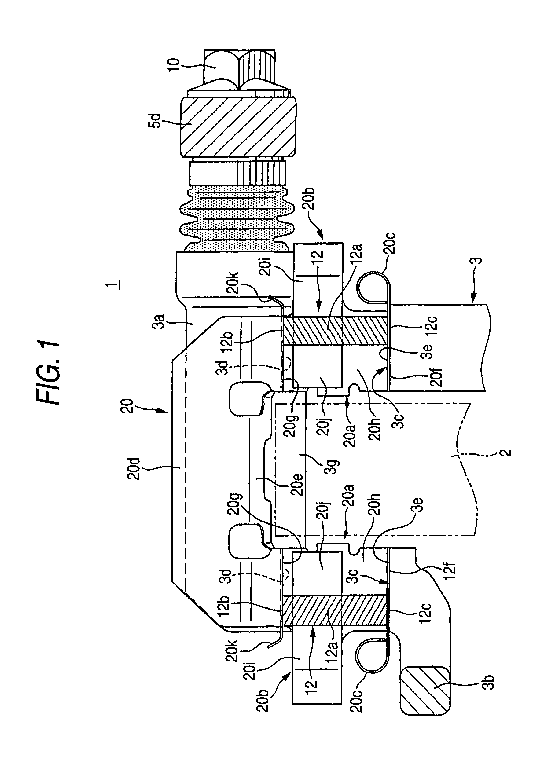
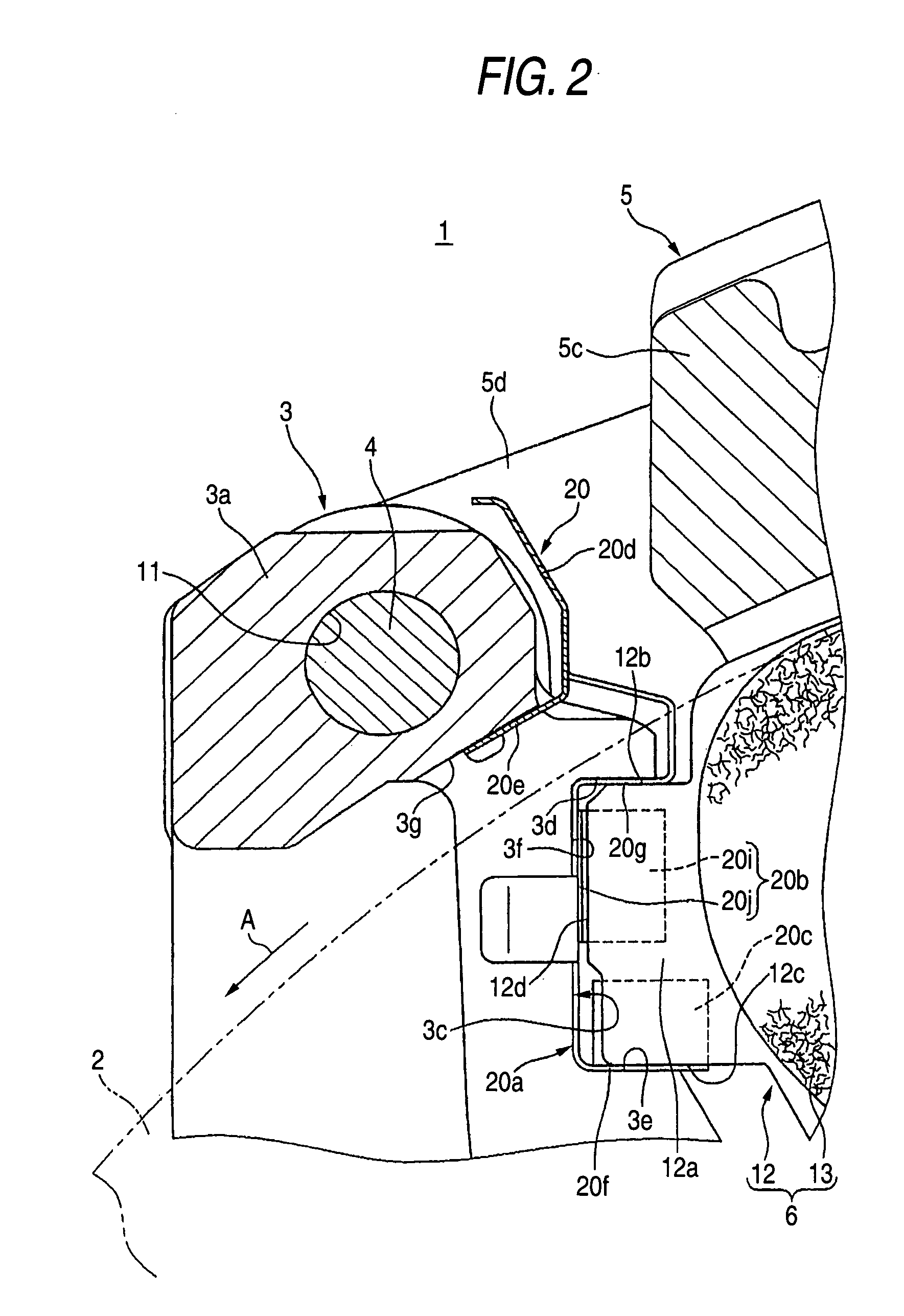
[0033]Embodiments of the present invention will be hereinafter described in detail with reference to the drawings. FIGS. 1–8 shows a first embodiment in which the invention is applied to a pin-slide-type disc brake. A disc brake 1 is composed of a disc rotor 2 that is to rotate together with a wheel, a caliper bracket 3 to be fixed to a vehicle body on one side of the disc rotor 2, a caliper body 5 that is supported by two caliper support arms 3a of the caliper bracket 3 via a pair of slide pins 4 so as to be movable in the disc axis direction, and a pair of friction pads 6 that are located inside an acting portion 5a and a reacting portion 5b of the caliper body 5 so as to be opposed to each other with the disc rotor 2 interposed in between.

[0034]The caliper body 5 is composed of the above-mentioned acting portion 5a and reacting portion 5b that are disposed on both sides of the disc rotor 2 and a bridge 5c that strides the outer periphery of the disc rotor 2 and connects the actin...

second embodiment

[0062]Next, the invention will be described with reference to FIGS. 9 and 11 in detail. In a pad retainer 41 according to this embodiment, the inner receiving piece 50f of each retainer portion 50a is formed with a pad falling-off preventive portion 50b having a springing-back function and a pad springing-back portion 50c that are continuous with each other. The pad falling-off preventive portion 50b and the pad springing-back portion 50c constitute a pad returning portion (i.e., a pad returning mechanism of the invention).

[0063]Each retainer portion 50a has an inner receiving piece 50f, an outer receiving piece 50g that is opposed to the inner receiving piece 50f, and a side piece 50h that connects the inner receiving piece 50f and the outer receiving piece 50g. The tops of the two retainer portions 50a are connected to each other by a link 50d. The link 50d is formed with an attachment piece 50e that is locked with the rotor groove 33h of the caliper support arm 33a. Each outer re...


PUM


Abstract

A disc brake for a vehicle has a caliper bracket fixed to a vehicle body, a pair of caliper support arms striding an outer periphery of a disc rotor in a disc axial direction, pad guide grooves formed in the caliper support arms so as to be opposed to each other, friction pads disposed on both sides of the disc rotor, the friction pads having ears projected from both side portions of a back plate thereof, and pad retainers disposed on the pad guide grooves, the ears of the friction pads being movably supported by the pad guide grooves via the pad retainers, wherein pad retainers each has pad returning portions for urging the friction pads away from the disc rotor.

Description

BACKGROUND OF THE INVENTION[0001]1. Field of the Invention[0002]The present invention relates to a disc brake for a vehicle that is used in vehicles such as automobiles and motorcycles. More specifically, the invention relates to the structure of pad retainers that are set in pad guide grooves of caliper support arms and movably support ears of back plates of friction pads.[0003]2. Description of the Related Art[0004]In general, in conventional disc brakes in which friction pads are hung and held so as to be movable in the disc axial direction in such a manner that ears projecting from both side portions of back plates of the friction pads are movably supported by pad guide grooves that are formed in caliper support arms of a caliper bracket, pad retainers made of a metal thin plate are interposed between the pad guide grooves and the ears. Each pad retainer is formed with pad returning mechanisms that are brought in contact with the disc-rotor-entrance-side and exit-side side faces...

Claims


Application Information

Patent Timeline
Patent Type & Authority Patents(United States)
IPC IPC(8): F16D65/40F16D65/097
CPCF16D65/0971F16D65/0972F16D65/0974F16D65/0977
Inventor ONO, TAKASHI
Owner HITACHI ASTEMO LTD
Why Eureka
Try Eureka