Reinforced brake rotor

Active Publication Date: 2007-05-22
LIN WARREN
View PDF25 Cites 43 Cited by
  • Summary
  • Abstract
  • Description
  • Claims
  • Application Information

AI Technical Summary

Benefits of technology

[0008]The present invention presents new rotor designs, devices, systems and methods for increasing the durability and braking performance of disc brake systems and their associated parts. Specifically, in certain emb

Problems solved by technology

However, such an upgrade usually would not significantly improve braking performance, and is most likely unnoticeable to the average automotive enthusiast.
The problem with replacing the OE brake rotors with larger diameter brake rotors is that many of the components of the OE brake system now also need to be replaced.
For example, th

Method used


Image

  • Reinforced brake rotor
  • Reinforced brake rotor
  • Reinforced brake rotor

Examples


Example

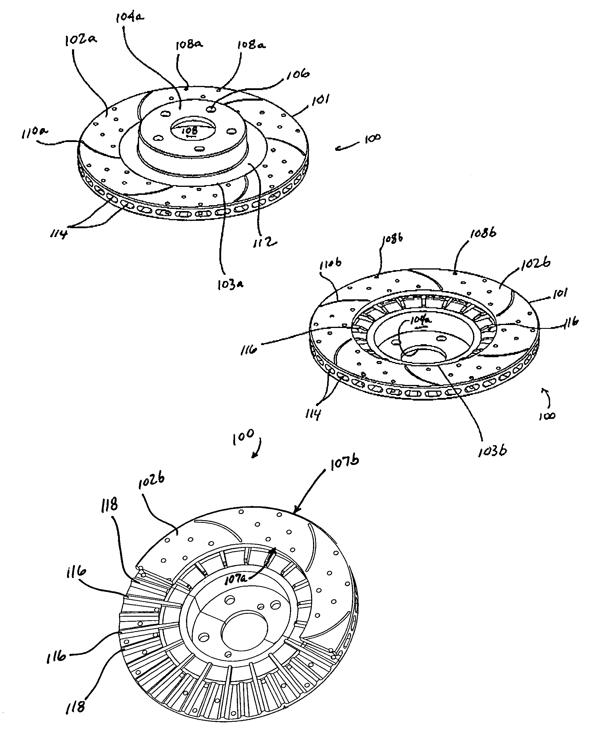
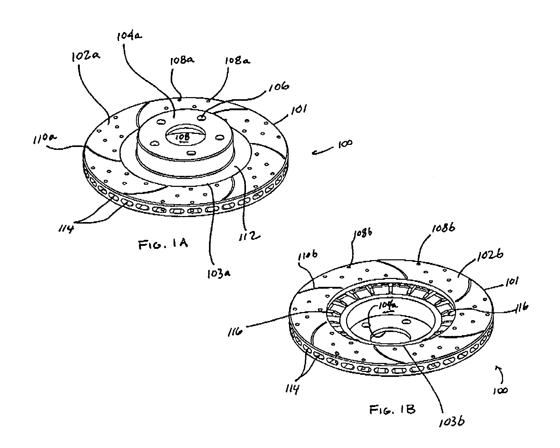
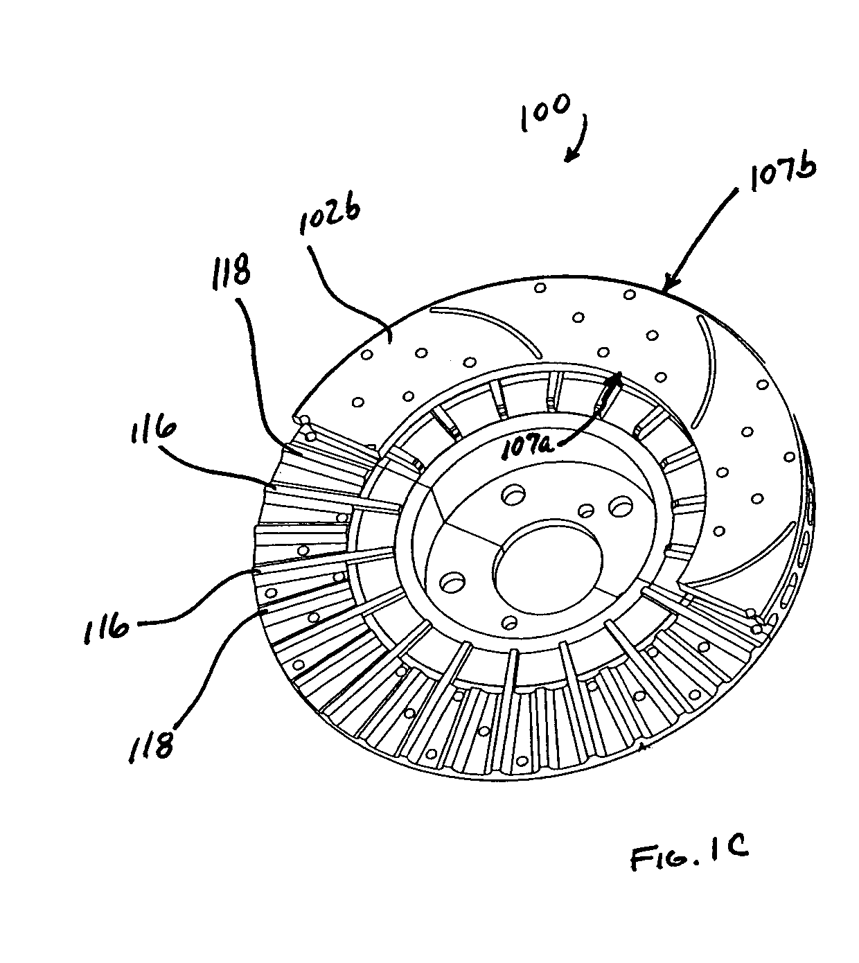
[0030]FIGS. 1A–1C illustrate one embodiment of the present invention. As shown, a disc brake rotor 100 includes an outer diameter 101, which is also the outer diameter of the outboard braking surface 102a and the outer diameter of the inboard braking surface 102b. Each braking surface also includes a respective inner diameter: inner diameter 103a with respect to braking surface 102a and inner diameter 103b with respect to braking surface 102b. The depth / width of each braking surface is illustrated by arrows 107a and 107b (see FIG. 1C).

[0031]Central to the brake rotor is a mounting portion 104, having an inner “bottom” surface 104a. The mounting portion may be a hat (as illustrated), or may contain a series of mounting holes or fasteners for mounting the rotor to a hub (i.e., a “hat-less” rotor). As illustrated, the hat included with the present embodiment includes a central opening 108 for receiving a central portion of a hub of a vehicle, and openings 106 for receiving (typically, ...


PUM


Abstract

Some embodiments of the present invention are directed to a brake rotor which may include a central mounting portion for mounting the brake rotor on a hub, a first annular braking surface and a second annular braking surface, where each braking surface includes an inner diameter and an outer diameter, a bridge provided between the central mounting portion and the inner diameter of at least one of the first and the annular braking surfaces and a plurality of ribs positioned proximate to the bridge.

Description

PRIORITY[0001]The present invention claims priority under 35 U.S.C. §119(e) of U.S. provisional patent application Nos. 60 / 462,110, filed Apr. 11, 2003, and 60 / 466,609, filed Apr. 30, 2003, each disclosure of which, in its entirety, is herein incorporated by reference. The present invention is related to co-pending and co-owned patent application Ser. No. 10 / 608,246, filed Jun. 27, 2003, the disclosure of which, in its entirety, is also herein incorporated by reference.FIELD OF THE PRESENT INVENTION[0002]Embodiments of the present invention are directed toward novel brake rotor designs for use with any disc braking system including those of motor vehicles, and methods of manufacturing the same.BACKGROUND OF THE INVENTION[0003]Generally, existing brake rotors include solid, non-venting rotor designs and venting designs, as disclosed in U.S. Pat. No. 5,878,848. Accordingly, conventional ventilated brake rotors generally include a pair of mutually spaced-apart annular disks that presen...

Claims


Application Information

Patent Timeline
IPC IPC(8): F16D65/12F16D65/847F16D69/00
CPCF16D65/12F16D65/847F16D2055/0037F16D2065/1308F16D2065/1316F16D2065/1328F16D2065/1384F16D2069/004
Inventor LIN, WARREN
Owner LIN WARREN
Why Eureka
Try Eureka