Mount assembly for electronic devices

a technology for mounting assemblies and electronic devices, applied in the direction of suction cups, machine supports, domestic objects, etc., can solve the problems of increasing the size, weight, and cost of the apparatus, and suffering from limitations

Active Publication Date: 2007-05-22
GARMIN
View PDF35 Cites 124 Cited by
  • Summary
  • Abstract
  • Description
  • Claims
  • Application Information

AI Technical Summary

Benefits of technology

[0008]The present invention solves the above-described problems and provides a distinct advance in the art of vehicle mounting assemblies for electronic devices. More particularly, the present invention involves a mounting assembly with a separable ball and socket joint that eliminates the need for a cradle interposed between a mount and an electronic device.

Problems solved by technology

While this type of prior art mounting apparatus is operable to mount a portable electronic device to a vehicle so that the device can be repositioned, it suffers from certain limitations.
The cradles of prior mount apparatuses increase the size, weight, and cost of the apparatus, for example, and require a user to loosen or tighten the screws or other fasteners each time the electronic devices are mounted to or removed from the cradles, and loosen and subsequently tighten the screws each time it is desired to re-position the electronic devices.

Method used


Image

  • Mount assembly for electronic devices
  • Mount assembly for electronic devices
  • Mount assembly for electronic devices

Examples


Embodiment Construction

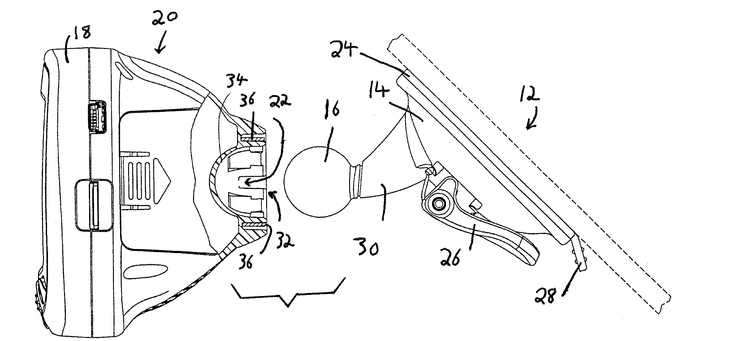
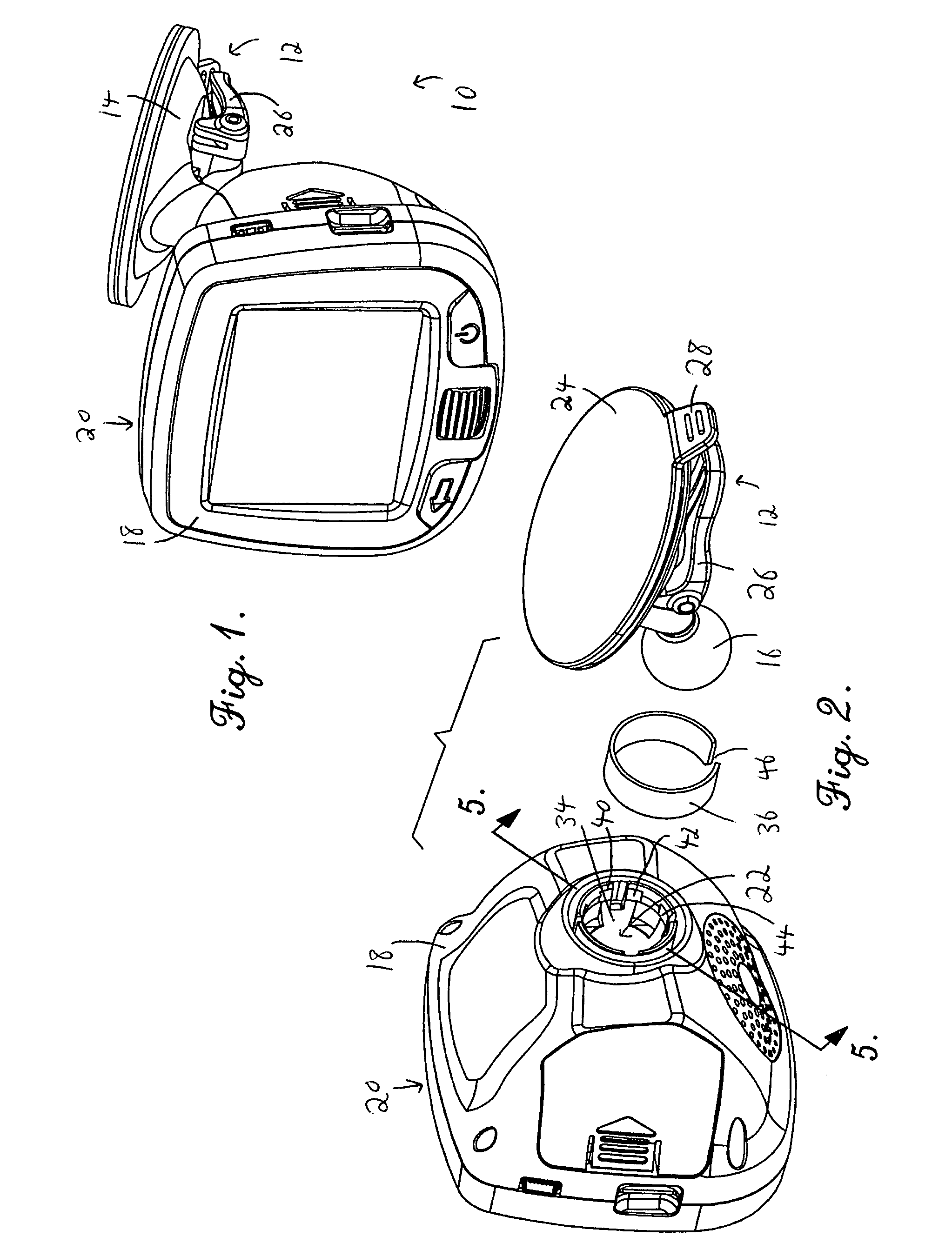
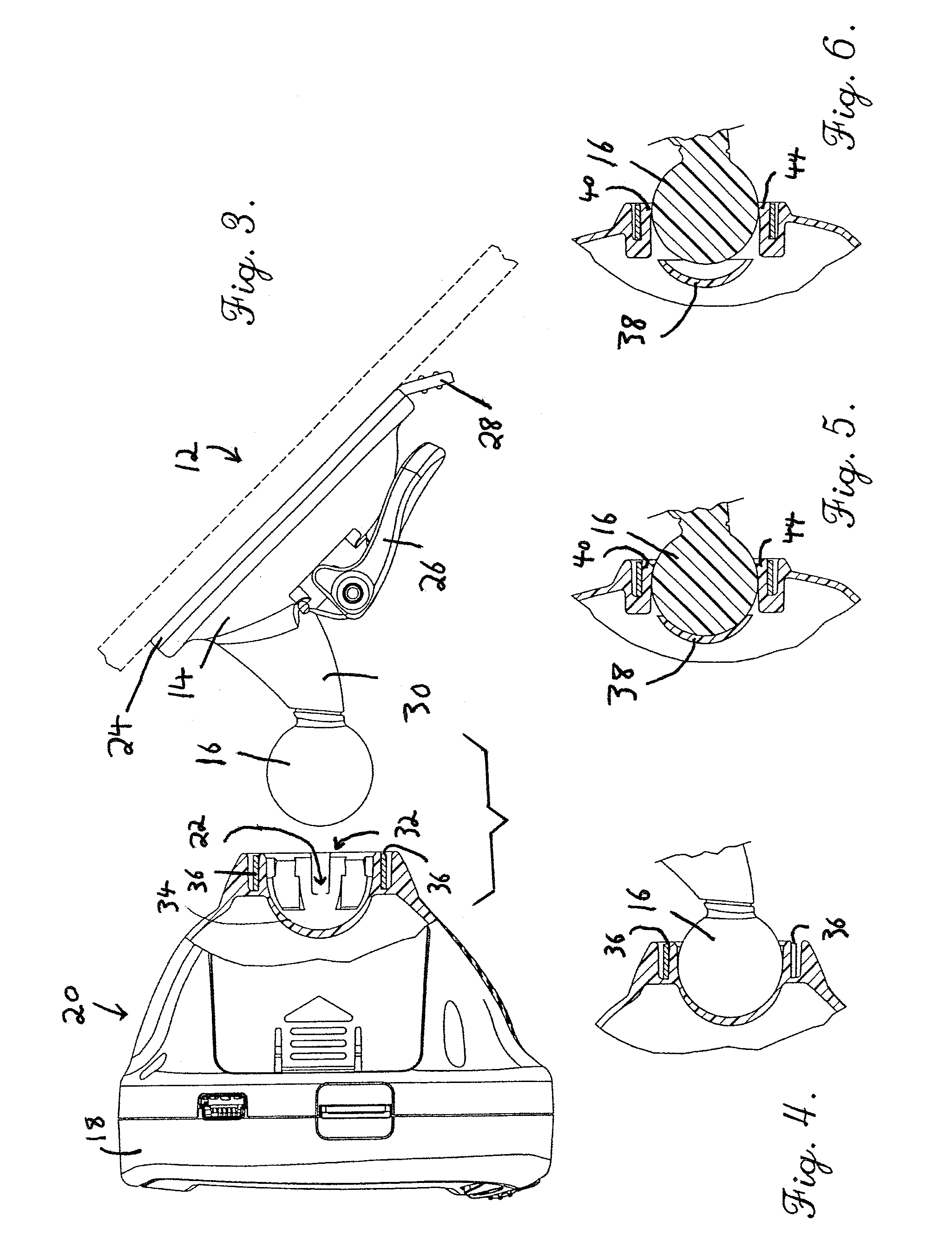
[0020]Referring initially to FIGS. 1 and 2, an exemplary mounting assembly for electronic devices employing the principles of the present invention is shown and designated generally by the reference numeral 10. The mounting assembly 10 comprises a mount 12 including a base 14 and a mounting ball 16; and a housing 18 for a portable electronic device 20, wherein the housing 18 presents a socket assembly 22 for receiving the ball 16.

[0021]The mount 12 removably secures to a surface of a vehicle (see FIG. 3), such as a windshield of the vehicle, and supports the electronic device 20 in view of a user, such as a vehicle driver or passenger. The mount 12 includes a rigid circular base 14 that is generally convex so as to curve away from the vehicle surface. A flexible sheet 24 is positioned between the base 14 and the vehicle surface for engaging the vehicle surface with a vacuum grip, wherein an air-tight seal is created between the flexible sheet 24 and the vehicle surface. The mount 12...


PUM


Abstract

A mounting assembly for portable electronic devices includes a mount (12) with a mounting ball (16) that mates with a socket assembly (22) formed in a housing (18) of an electronic device (20). The socket assembly includes an orifice (32) formed in the back of the housing, a seat (34) positioned in the orifice for matingly receiving the ball, and a spring element (36) partially surrounding the seat. The seat includes a concave center portion (38) and a plurality of flexible, interconnected arms (40,42,44) extending from the concave center portion. The spring element substantially encircles the flexible arms to allow the flexible arms to flex outward when receiving the ball and to then contract inwardly to contact the ball when the ball is seated fully in the seat.

Description

BACKGROUND OF THE INVENTION[0001]1. Field of the Invention[0002]The present invention relates to the field of mounting assemblies for electronic devices. More particularly, the invention relates to a mounting assembly with a ball and socket joint, wherein the ball and socket are easily separable for quick installation and removal of an electronic device.[0003]2. Description of the Prior Art[0004]The use of electronic devices in vehicles has increased in recent years. For example, it is increasingly more common to see electronic devices such as global positioning satellite (GPS) devices, portable telephones, radios and personal digital assistants (PDAs) mounted within vehicles either permanently or, in the case of portable electronics, removably. Many of these devices have displays which visibly communicate information to one or more users. Thus, it is advantageous to be able to adjust a position and angle of such devices to provide maximum viewing capability to the user or users. Po...

Claims


Application Information

Patent Timeline
Patent Type & Authority Patents(United States)
IPC IPC(8): A47F5/00
CPCB60R11/0258F16C11/0657F16M11/14F16M13/00F16M13/02F16M13/022F16C11/069B60R2011/0026B60R2011/0056B60R2011/0089Y10T403/32737Y10T403/32721
Inventor KALIS, ROBERT M.REESON, JOSHUA C.LANGNER, DALE R.SKELTON, PAUL E.
Owner GARMIN
Why Eureka
Try Eureka