Method and apparatus for three dimensionally displaying eyeground and measuring coordinates thereof

a three-dimensional display and coordinate technology, applied in the field of three-dimensional display of eyeground and measuring its coordinates, can solve the problems of inconvenient use, inability to accurately connect photos, and inability of specialized physicians to easily make precise diagnosis using photos, etc., to achieve accurate reproduction

Inactive Publication Date: 2007-05-22
RIKEN
View PDF13 Cites 26 Cited by
  • Summary
  • Abstract
  • Description
  • Claims
  • Application Information

AI Technical Summary

Benefits of technology

[0015]The present invention aims to solve the aforementioned problems. More explicitly, an object of the present invention is to provide methods and apparatus that even if an eye ball is deformed from being a precise spherical surface, a three dimensional image of the eyeground can be accurately reproduced, and quantitative data on sizes and positions of abnormal blood vessels, retina detachment, tumors, etc. can be created from the above mentioned three dimensional image, and the data can be used as time dependent data of the patient and for an epidemic database by cubicly displaying the eyeground and measuring coordinates three dimensionally.
[0019]Because imaging positions are shifted each time by a predetermined amount h and a number of eyeground areas including superimposed portions d are photographed, and the number of images are pasted on the eyeball template based on the eyeball parameter g in the image pasting step (F), a three dimensional image of the eyeground can be precisely produced, so this image is displayed in the display device in the three dimensional image displaying step (H) to help specialized physicians and patients understand the situation.

Problems solved by technology

However, the field of view of the eyeground camera is narrow at about 50 degrees, so even a specialized physician cannot easily make a precise diagnosis using a photo.
However, because the eyeground is spherical and a photo of it is a projection of part of the eyeground on a plane, photos taken are not continuous and cannot be precisely connected.
Eyeground photos connected as described above consist of planes developed from the spherical eyeground, so only a specialist physician can precisely diagnose such photos, applying extensive expertise of the construction of an eyeball, and a physician without specialized knowledge or a patient cannot understand the images.
Therefore, if the lens of a living eye is modeled with a single lens and the shape of the eyeground is regarded to be substantially a sphere, in the case of a deformed eye ball, if any, the reproduced eyeground differs from the actual eyeground, so the fact that the reproduced eyeground cannot be used for precision diagnostics or a database of eyeground data, is a problem.
As a result, camera positions and poses when each image is photographed can no longer be estimated, so parameters for a single lens also cannot be obtained, and even the shape of the eyeground might not be reproducible.

Method used


Image

  • Method and apparatus for three dimensionally displaying eyeground and measuring coordinates thereof
  • Method and apparatus for three dimensionally displaying eyeground and measuring coordinates thereof
  • Method and apparatus for three dimensionally displaying eyeground and measuring coordinates thereof

Examples


Embodiment Construction

[0044]The present invention is described in more detail referring to the drawings.

[0045]In each drawing, common portions are identified with the same numbers, and no duplicate description is given.

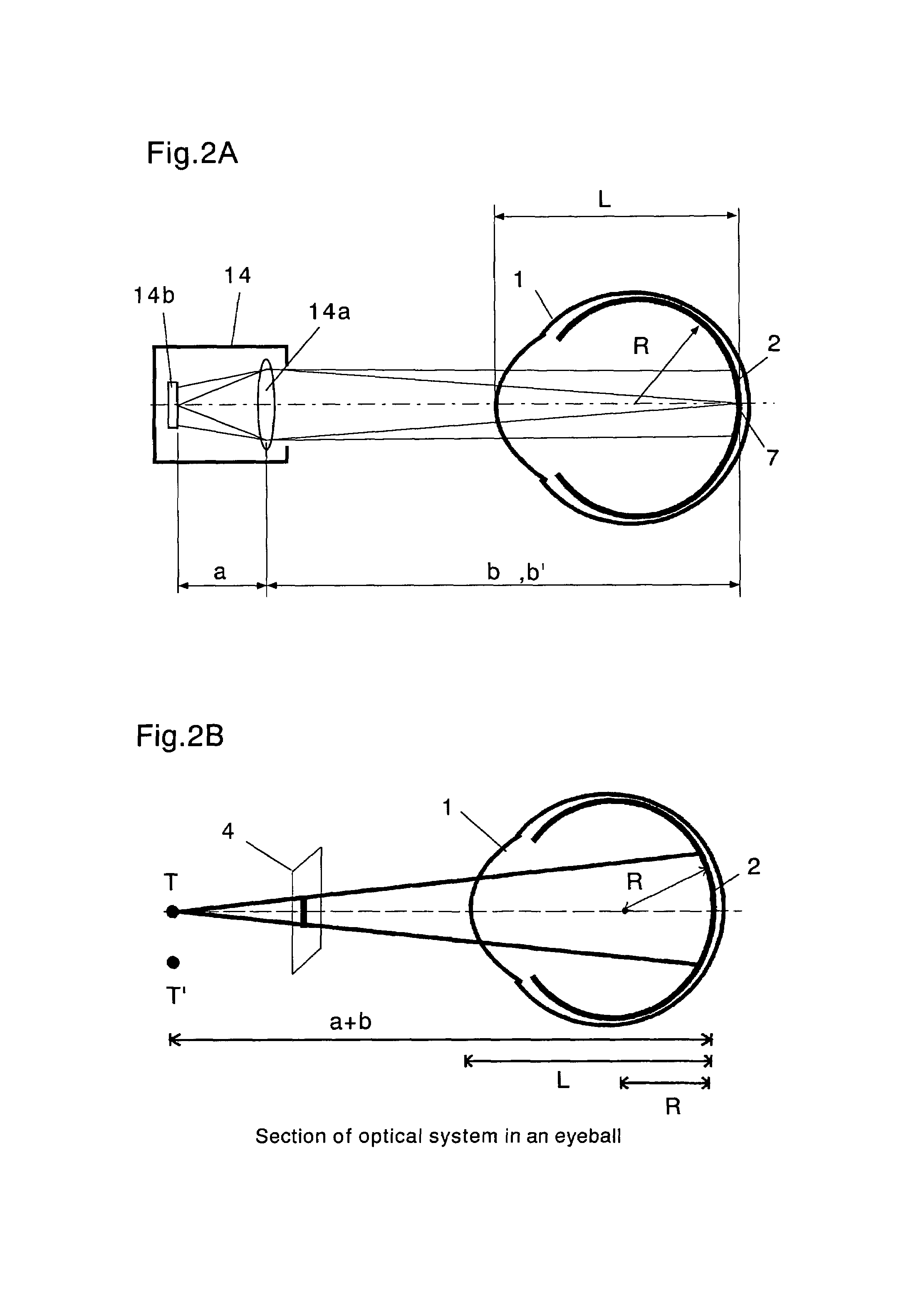
[0046]FIGS. 2A and 2B show the positional relationship between the eyeball 1 and the imaging device 14.

[0047]FIG. 2A is a view that also shows the optical system of the imaging device 14, and FIG. 2B is a schematic view omitting the optical system of the imaging device 14. The principles of the present invention are described using these figures.

[0048]In FIG. 2A, 14a represents the lens of the imaging device 14 (eyeground camera), and 14b is a CCD that records images. When the imaging device 14 takes a picture of the eyeground, the following equation (1) is known to hold by omitting the presence of the eyeball 1.

a−1+b−1=f−1  (1)

Where f is the focal distance of the lens 14a.

[0049]Because the eyeball 1 has a refractive index n, which is substantially constant, when the size L of the eyeball...


PUM


Abstract

Presented are a shape measuring step (A) in which the size L of an eyeball 1 and the shape R of the eyeground 2 are measured, an eyeball setting step (B) for setting an eyeball template 3, an eyeground image taking step (C) for taking images of the eyeground including superimposed portions d by shifting the imaging positions, a parameter setting step (D) for obtaining an eyeball parameter g that represents the positional relationship between the eyeground and images, an image pasting step (F) for pasting a number of images on the eyeball template, and a three dimensional image displaying step (H) for displaying three dimensional eyeground images 5 on the eyeball template on a display device 16.

Description

[0001]This application claims priority of Japanese Application No. JP-2002-189265, filed on Jun. 28, 2002. The entire disclosure of the above application is hereby incorporated by reference.BACKGROUND OF THE INVENTION[0002]1. Technical Field of the Invention[0003]The present invention relates to methods and apparatus for displaying an eyeground three dimensionally and measuring its coordinates from photos of the eyeground.[0004]2. Description of the Related Art[0005]An eyeground means the inner portion of an eyeball, and is one of the few portions of a human body wherein blood vessels and nerves can be directly observed. Conventionally, dedicated eyeground cameras have been used to observe the eyeground and diagnose abnormalities in blood vessels, retinas, tumors, etc.[0006]The eyeground camera illuminates the interior of an eye through a pupil of a patient, and at the same time the camera takes a picture of part of the eyeground on photo film or CCD. However, the field of view of t...

Claims


Application Information

Patent Timeline
Patent Type & Authority Patents(United States)
IPC IPC(8): A61B3/10A61B3/12A61B3/14G06T1/00H04N7/18
CPCA61B3/12A61B3/145
Inventor YOKOTA, HIDEOMAKINOUCHI, AKITAKEYABE, HIROO
Owner RIKEN
Why Eureka
Try Eureka