Communication plug with balanced wiring to reduce differential to common mode crosstalk

a technology of communication plugs and balanced wiring, applied in the direction of coupling devices, two-part coupling devices, electrical equipment, etc., can solve the problems of increasing the cost of the system, undesirable signals, and the inability of each wire in the wire-pair to pick up electrical noise, so as to reduce the tendency for differential to common mode crosstalk conversion, improve alien next performance, and improve crosstalk performance

Active Publication Date: 2007-05-22
COMMSCOPE INC
View PDF84 Cites 91 Cited by
  • Summary
  • Abstract
  • Description
  • Claims
  • Application Information

AI Technical Summary

Benefits of technology

[0009]The present invention provides communications connectors, in particular communications plugs, that may have improved crosstalk performance. As a first aspect, embodiments of the present invention are directed to a communications plug, comprising: a mounting substrate; a plurality of pairs of output terminals; and first, second, third and fourth pairs of conductors. The first, second and fourth pairs of the output terminals are arranged in immediately adjacent relationship, and a third pair of output terminals includes output terminals that are separated from each other such that a first output terminal of the third pair is positioned between the first and second pairs of output terminals, and such that a second output terminal of the third pair is positioned between the first and fourth pairs of output terminals. Each of the first, second, third and fourth pairs of conductors engages the mounting substrate and is attached for electrical communication with a respective one of the output terminals. The third pair of conductors has at least two locations in which the conductors of the pair cross each other, and is arranged such that, between the crossover locations, the third pair of conductors forms an expanded loop that brings segments of the third conductor into closer proximity to the second and fourth pairs of conductors than to the first pair of conductors. In this configuration, the plug (which in some embodiments is a communications plug) may exhibit a reduced tendency for differential to common mode crosstalk conversion, particularly between the third pair of conductors and the second and fourth pairs of conductors, which can improve alien NEXT performance between channels, particularly at elevated frequencies.
[0010]As a second aspect, embodiments of the present invention are directed to a communications plug, comprising: a mounting substrate; a plurality of pairs of output terminals; and first, second, third and fourth pairs of conductors. The first, second and fourth pairs of the output terminals are arranged in immediately adjacent relationship, and a third pair of output terminals includes output terminals that are separated from each other such that a first output terminal of the third pair is positioned between the first and second pairs of output terminals, and such that a second output terminal of the third pair is positioned between the first and fourth pairs of output terminals. Each of the first, second, third and fourth pairs of conductors engages the mounting substrate and is attached for electrical communication with a respective one of the output terminals. The third pair of conductors has at least two locations in which the conductors of the pair cross each other. The third pair of conductors is arranged such that, between the crossover locations, the third pair of conductors forms an expanded loop that brings segments of the third conductor into relative proximity to the first, second and fourth pairs of conductors. The positioning of the second, third and fourth pairs of conductors substantially prevents the conversion of differential mode crosstalk to common mode crosstalk between (a) the second and third pairs of conductors and (b) the third and fourth pairs of conductors. This configuration can reduce the alien NEXT experienced between a plug-jack combination, especially at elevated frequencies.
[0011]As a third aspect, the present invention is directed to a mounting substrate for a communications plug. The mounting substrate includes: a body formed of a dielectric material; a spreading member mounted to an upper surface of the body, the spreading member being configured to receive respective conductors on opposite sides thereof, and capture members mounted to opposing edge portions of the upper surface of the body. Each of the capture members is configured to receive a pair of conductors and maintain the pairs of conductors at a given distance from conductors received in the spreading member channels. This configuration can position the respective conductors such that alien NEXT performance is improved.

Problems solved by technology

Each wire in a wire-pair is susceptible to picking up electrical noise from sources such as lightning, automobile spark plugs and radio stations to name but a few.
Of greater concern, however, is the electrical noise that is picked up from nearby wires or pairs of wires that may extend in the same general direction for long distances and not cancel differentially on the victim pair.
In all of the above situations, undesirable signals are present on the electrical conductors that can interfere with the information signal.
However, a problem case may be “pair 3” of one channel crosstalking to “pair 3” of another channel, even if the pair 3 plug and jack wires in each channel are remote from each other and the only coupling occurs between the routed cabling.
However, the inclusion of shields can increase cost of the system.
However, this is typically impractical because bundling of cables and patch cords is common practice due to “real estate” constraints and ease of wire management.
In spite of recent strides made in improving mated connector (i.e., plug-jack) performance, and in particular reducing crosstalk at elevated frequencies (e.g., 500 MHz—see U.S. patent application Ser. No. 10 / 845,104, entitled NEXT High Frequency Improvement by Using Frequency Dependent Effective Capacitance, filed May 4, 2004, the disclosure of which is hereby incorporated herein by reference), many connectors that rely on either these teachings or those of the '358 patent can still exhibit unacceptably high alien NEXT at very high frequencies (e.g., 500 MHz).

Method used


Image

  • Communication plug with balanced wiring to reduce differential to common mode crosstalk
  • Communication plug with balanced wiring to reduce differential to common mode crosstalk
  • Communication plug with balanced wiring to reduce differential to common mode crosstalk

Examples


example

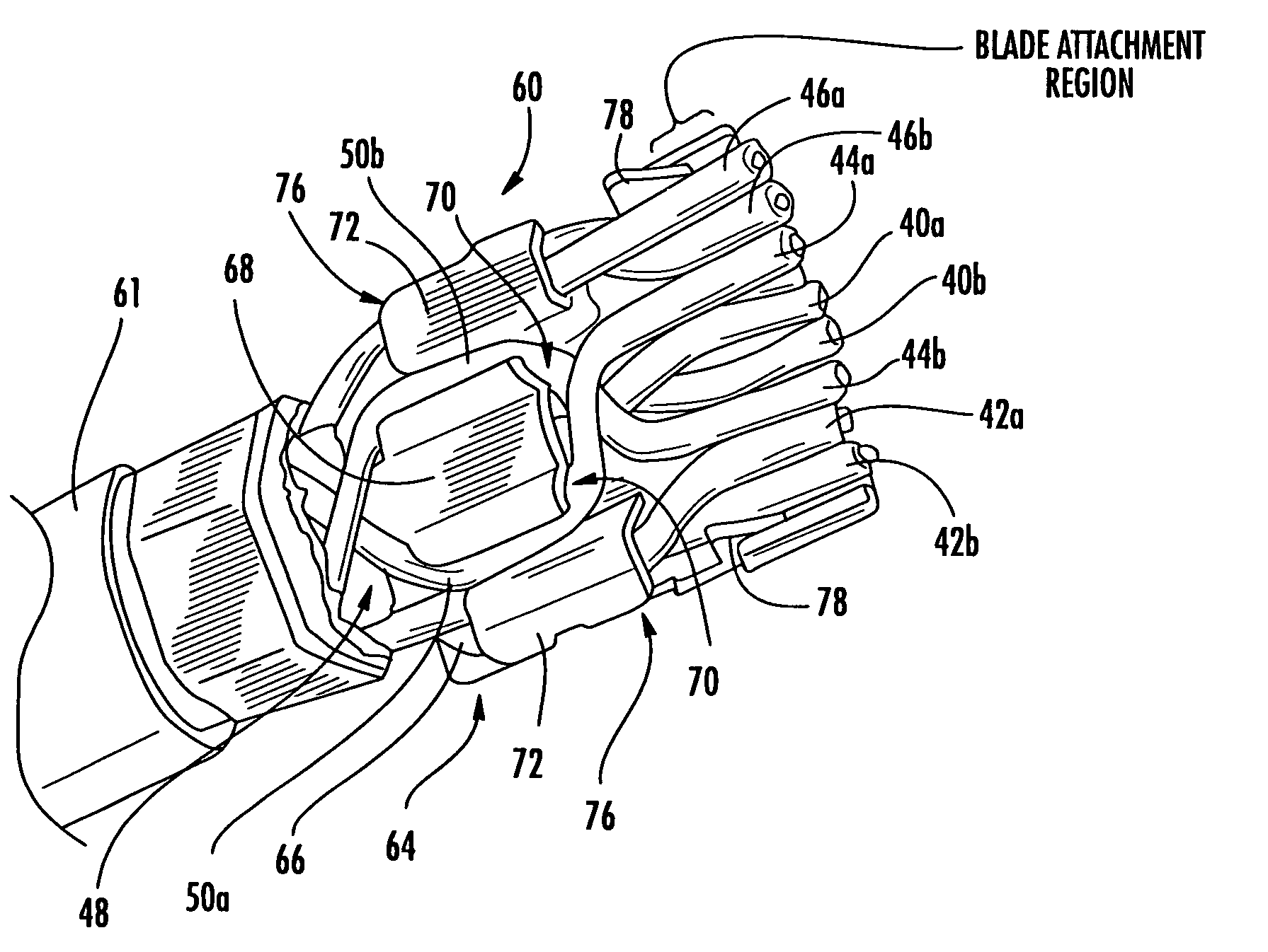
[0044]Plugs having the configuration illustrated in FIGS. 3 and 5 above were constructed of conventional materials. The conductors of pair 3 were formed into an expanded loop having a width of 0.2 inch and segments having a length of about 0.22 inch. This spacing positioned the segments of pair 3 about 0.050 inch from the conductors of pair 1 and about 0.030 inch from the conductors of pairs 2 and 4. Differential to common mode scattering testing was then conducted on this plug and a conventional plug (Model No. GS8E, available from Systimax Solutions, Inc., Richardson, Tex.). The three plugs were each connected to the same category 6 jack, and modal decomposition tests were performed for differential to common mode conversion between (a) pair 3 and pair 2 and (b) pair 3 and pair 4 using a system and procedures described in U.S. Pat. Nos. 6,407,542; 6,571,187; and 6,647,357 to Conte.

[0045]The results of the testing are shown in FIGS. 11–14. FIGS. 11 and 12 show the differential to c...


PUM


Abstract

A communications plug includes: a mounting substrate; a plurality of pairs of output terminals attached to the mounting substrate; and first, second, third and fourth pairs of conductors. The first, second and fourth pairs of the output terminals are arranged in immediately adjacent relationship, and a third pair of output terminals includes output terminals that are separated from each other such that a first output terminal of the third pair is positioned between the first and second pairs of output terminals, and such that a second output terminal of the third pair is positioned between the first and fourth pairs of output terminals. Each of the first, second, third and fourth pairs of conductors is attached for electrical communication with a respective one of the output terminals. The third pair of conductors has at least two locations in which the conductors of the pair cross each other, and is arranged such that, between the crossover locations, the third pair of conductors forms an expanded loop that brings segments of the third conductor into closer proximity to the second and fourth pairs of conductors than to the first pair of conductors.

Description

RELATED APPLICATIONS [0001]The present application claims priority from U.S. Provisional Patent Application Ser. Nos. 60 / 633,783, filed Dec. 7, 2004, entitled Communication Plug with Balanced Wiring to Minimize Differential to Common Mode Crosstalk and from U.S. Provisional Patent Application Ser. No. 60 / 648,002, filed Jan. 28, 2005, entitled CONTROLLED MODE CONVERSION PLUG FOR REDUCED ALIEN CROSSTALK, the disclosures of which are hereby incorporated herein in their entireties.FIELD OF THE INVENTION [0002]The present invention relates generally to communication connectors and more particularly to near-end crosstalk (NEXT) compensation in communication connectors.BACKGROUND OF THE INVENTION [0003]In an electrical communication system, it is sometimes advantageous to transmit information signals (video, audio, data) over a pair of wires (hereinafter “wire-pair” or “differential pair”) rather than a single wire, wherein the transmitted signal comprises the voltage difference between th...

Claims


Application Information

Patent Timeline
Patent Type & Authority Patents(United States)
IPC IPC(8): H01R24/00H01R24/58
CPCH01R13/6467H01R24/62
Inventor PHARNEY, JULIAN
Owner COMMSCOPE INC
Why Eureka
Try Eureka